terrain from contours

This has been discussed before…hope I didn’t miss anything.

The idea is to generate a 3d model of a real patch of earth, starting from contour lines.

Here are some possible ways of doing it:

get an image of the contours and their heights
set it up as a background in Blender
lay a grid over it
select all grid points
(paint) deselect all the points in the lowest lying region
move the selected points the appropriate distance up z using proportional edit
deselect the next lowest lying points
etc
(important to choose the right radius for prop edit)

from an image, generate a height map using Blackart or some other soft
apply it as a texture to a grid in Blender
hit noise and smooth until a good result is achieved
(not very precise)

clean up a pixel image
convert it to a vector image (inkscape or wintopo)
import the resulting lines into Blender
move the lines along z to their correct heights
apply some magic script to create a surface from the edges/verts
(it can be done in Sketchup)

I haven’t had much success with the third method, not knowing enough about meshes in Blender. Any ideas would really be appreciated.

Also, ideas about other ways of doing this…

Attachments


Can you get the date in another format than an image? Say… a series of coordinates and elevations? Then you could python script something.

detele post

I personally love to see something like that in Blender
: being able to build sites from contours with real coordinates. I think the easiest way to transform the image into vector is: gimp (increase the contrast)->inkscape(trace contours and save as .svg) ->blender

If all you have is an image, you may want to import it into Illustrator and do a “LiveTrace” on it. This will convert it to curves. Then you can export that as a SVG and build up your terrain as you see fit inside Blender.

Thanks everyone!

macouno, converting the image to vector data, importing into blender and manually assigning heights to the various contour lines, effectively creates a 3d grid of points which follow the required surface. Then we need a process like shift+F but for 3d surfaces! Is there such a script out there, I am no python scripter myself.

studioa, I read your earlier post on the same topic:
http://blenderartists.org/forum/showthread.php?t=90675&highlight=terrain+contours
Like you say it can be done in sketchup, so of course there is a way in blender too.
When I use the inkscape route (potrace) for vectorisation, because of line thickness in the original image, the lines become planar surfaces. In other words, every data point is duplicated, which is not good. Do you know a way around this…I guess there must be a setting that can be tweaked…

atom, I would guess that the livetrace function in illustrator does the same as the image trace function in inkscape. It still leaves us with the problem of skinning a z-distorted mesh. (not really viable to do it manually!)

Hi,
I think converting raster contour data to vector would only work if data is clean as in the first post, so if you want to get data from scanned survey plan or smilar you need to deal with extra lines. If terrain size is not very large, vectorizing contours by hand takes less time than cleaning those extra lines in image man. program. Also vectorizing isn’t poly-friendly but you can retopo a subdivided face onto that terrain.

I couldn’t found an easier solution like in sketchup. Easiest way to create contours in blender i think using curves, than convert to mesh and f->skin faces. Also give a try to surface->nurbs curve (model first contour and extrude).

Terrain that modeled in sketchup can be exported to blender using exporter or heightmap (fog method).

Do you want to edit the terrain preciously?

Why not use it like a conventional height map colour code yourself some heights for different shades of gray. Fill in the gaps between contours blend the edges. Use as heightmap and voila.

Hi karamelo, I get your point…sometimes it may be quicker to trace contours manually rather than clean up the image. It sounds like you’ve been through this yourself! Your reply gives a lot of interesting ideas. Just a few questions:

Also vectorizing isn’t poly-friendly

Do you mean than automatic vectorizing does not produce nicely spaced vertices? Or it produces too many vertices?

but you can retopo a subdivided face onto that terrain.
Are you saying create a terrain from the vector data and then retopo a fresh 2d grid onto that terrain? That’s a cool idea

than convert to mesh and f->skin faces
How would you do this exactly? If you have a series of contours set at different heights, I’m not aware of any command that would automatically skin the whole surface. Would you work around the model and skin one section at a time?

heightmap (fog method)
Not familiar with fog method. If I made the terrain in SU then saved a 2d image shot from above, would that work as a heightmap in blender?

Also, the only way I’ve found to create bumps in a flat mesh with a heightfield is by using the noise function in mesh tools. Is there another way?

Do you want to edit the terrain preciously?
Not sure what you mean here.

Hi Wookie, I like the sound of your idea. Would you use Gimp maybe to do this?

Hi,

Do you mean than automatic vectorizing does not produce nicely spaced vertices? Or it produces too many vertices?

Are you saying create a terrain from the vector data and then retopo a fresh 2d grid onto that terrain? That’s a cool idea

Yes.

Not familiar with fog method. If I made the terrain in SU then saved a 2d image shot from above, would that work as a heightmap in blender?

Also, the only way I’ve found to create bumps in a flat mesh with a heightfield is by using the noise function in mesh tools. Is there another way?

Here i described 3 methods to export a terrain from sketchup.

Gradient material is better, you can lose proportion of contours with fog method.

Would you work around the model and skin one section at a time?
Yes:

Do you want to edit the terrain preciously?
Not sure what you mean here.
What i wanted to say, how do you want to use blender, as a design tool or a visualisation tool?

Thanks for all that info!
I’ve tried the fog method and the gradient method. Great techniques! I did not know these possibilities were hidden inside of sketchup! Like you say the gradient method seems more likely to produce a more precise result.

This brings up another question. About precision. When applying a heightmap to a mesh, Blender must use a formula which converts probably the brightness parameter to height. It would be interesting to know more about this conversion…is it linear or non-linear?

Otherwise I am just going on faith that the mesh produced from the heightmap will be faithfull to the original. Maybe I’m over-thinking this!

I am using these terrains in my architectural work, so primarily they are a design tool but also could be used in presentations, etc. So they need to be pretty accurate. If I can have one or two techniques for quite quickly building a terrain, it would be very useful.

Also, to create a terrain from a grid and a heightmap, is the correct way via “noise” in “mesh tools”? So far what I’ve tried is to keep hitting “noise” until the heights measure up OK against the grid…or is there another way?

Thanks for that how-to on tracing curves over a background image. I think that can also produce good results, and like you say, it saves all the problems of cleaning up the original image. I would be great to be able to use the 3d nurbs skinning tool, but the limitation of having the same number of control points in each curve will usually be a problem.

I really appreciate your input here and the trouble you have taken. I’ve certainly learned some great new techniques!

To me the answer lies in producing a terrain by any of the above methods and then retopo a fresh grid of the right resolution onto that terrain. That produces a very pretty model which is also easily editable…say if a part of the site needs to be levelled.

I’ve been working on a project like this for the past several months. There is, unfortunately, no good way to do this in Blender.

  1. You can import .svg files into Blender. This is great because it does all the tracing for you. However, the types of curves that it imports as (without option) are just spline cures which cannot be “lofted” or skinned. Blender does not allow the conversion from one type of curve to another. Not to mention that NURBs curves from the Add -> Curves -> NURBs Curve menu cannot be lofted, but NURBs curves from the Add -> SURFACES -> NURBs Curve CAN be lofted. Also, all the curves that are lofted have to have exactly the same number of vertices. No, there’s no easy way to do that.

  2. You can Fill, Beautify fill, loft, etc mesh lines as well, fairly automatically. Additionally, you don’t have to have the same number of verts in each curve to loft from one to another. And there’s a beautiful tool called “Bridge” that comes in the new builds which will interpolate intermediate contours.

The problem with both methods above is that neither is able to take into account the fact that these are TERRAIN contours. There are lots of way to skin these contours that are impossible in real life. Either of these methods is tolerably accurate and easy provided that you have only a very simple hill. Several concentric circles that don’t do anything very strange works just fine. This is not, however, the case with the terrain on our beloved Earth.

The only method that I’ve found that gets anywhere near reasonable ease and accuracy is to use a make-shift height map as a displacement texture. Yes, with gamma correction, value interpolation and the displacement modifier’s algorithm there’s a lot of guess work, but it’s the best I’ve found. Here are the steps:

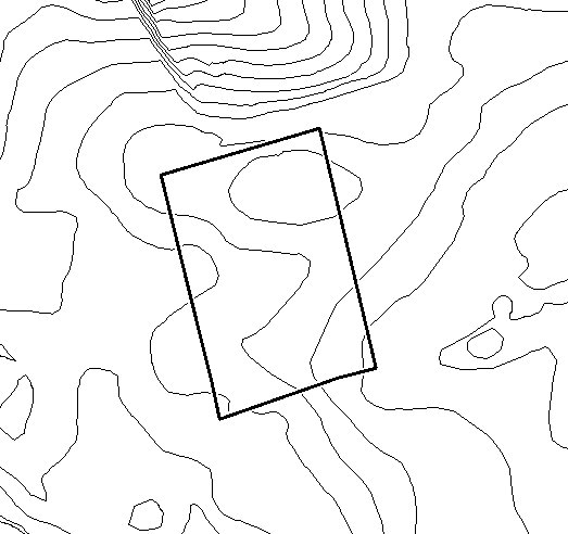
Note: You must have a few things for this technique. You must have a rasterized image of your contours (bitmap, png, jpeg, tif, gif, really doesn’t matter except for compression rate). You must have an image manipulator (I used the GIMP, but you need something with a fairly robust filter set i.e. something that can Gaussian blur a lot).

  1. Close all your contours. All the lines must either be closed circles or go off the page. Nothing other than contours. Erase all topographical markers.

  2. Count the number of contours you have, specifically the gaps between the contours (I had 15). Divide 255 by that number (255/15 = 17). This is your differential.

  3. Set your paint-bucket (or other fill tool) to a 255 white and to fill similar colors (rather than fill whole selection).

  4. (You will want to use a new layer and use “sample merged” as it’s called in the GIMP. If you have the actual lines in the final it can cause problems). Starting with the highest elevation, fill that with pure white. Subtract your differential from that (255 - 17 = 238) and use that as your new color. Fill the next lower contour gap with that color. Rinse, repeat. (238 - 17 = 221; fill; 221 - 17 = 204; fill; etc.)

  5. You should end up with a lovely banded version of your contour lines progressing from completely white at the highest point(s) down to completely black at the lowest.

  6. Then you Gaussian blur the heck out of it. On an 8000x8000 image I used a blur radius if about 650. The goal is to eliminate the appearance of any solid colors without completely destroying the detail. This is where the guesswork starts. You’ll have to try different amounts of blurring to find out which one sufficiently eliminates the banding without destroying detail that you really want.

  7. Now you have an image that you can use as a displacement map in a texture. (I recommend a displacement modifier instead of checking “disp” in the influence panel because you can do some subsurfing and smoothing with more control if you can place the disp in the stack where you want it). The “strength” value in the displace modifier will allow you to make the elevation what it should be for the given size.

Things to consider:
Gaussian blur tends to clip whites. Your highest peak(s) and lowest valleys will be too flat if you don’t do some color correction. Make sure you’ve got plenty of “room” in your color space to prevent crushing several very bright grays into plain white (or darks into plain black).

Avoid banding, where possible. Banding = data loss. There might not be anything you can do about it, but wherever there is a band, that place will be perfectly flat.

It will look funny when you take it into Blender. You’re going to have to do a lot of work with subsurfing before and after your disp, and I would also recommend the “smooth” modifier. It smooths like subsurf, but without adding geometry. Also, more polys is not better. You have to find the sweet spot. Too many polys and any subsurf or smooth will merely bevel the edges of your very “pixelated” terrai without getting rid of the “pixels.”

There are other tools out there for converting 2D contours to 3D terrain and I’m hoping to find something that will create a file type that Blender recognizes (check out the add-ons too, Blender will read almost anything.)

Good luck…

@hurleyman thanks for that detailed explanation - i’d like to work through your procedure when i have some time…

some time after this post, i discovered the point-cloud-skinner script. (i was using 2.49 at the time…)
an excellent script, works something like this:

  • get contour lines as individual mesh objects into blender somehow, either by vectorizing an image. or sometimes it’s easier/quicker to just trace over a background image

-set the contours at their correct heights

  • (probably) join them all into one mesh. then in edit mode delete edges and faces

  • now you have a “point cloud” which the script can operate on

  • give the script a few starting parameters and go

  • a great terrain - maybe fill a few holes and then retopo on to a fresh mesh

  • nice!

  • probably doesn’t work in 2.5x! (do it in 2.49 and append?)