Hi there, lol, it does not transform Cycles into a spectral renderer, would be too cool (appleseed is open-source spectral renderer, NM range definable at compile time. I’m curious about that myself, i’d like to test if it’s possible to Render Infrared, like Infrared photography)
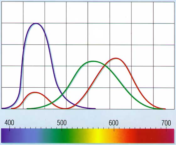
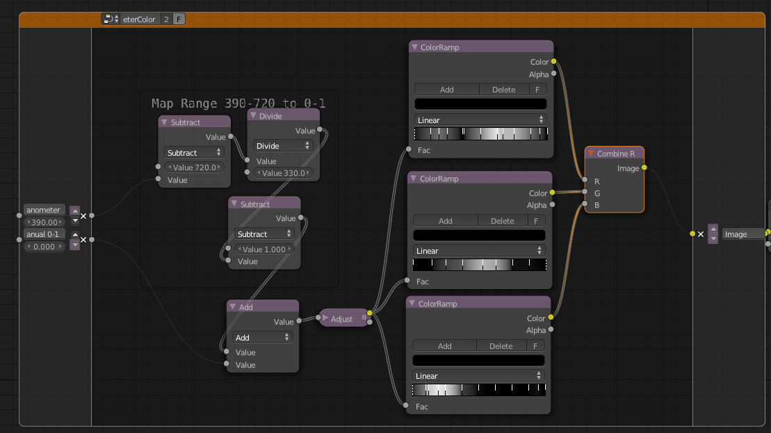
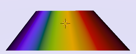
My NodeGroup simply transforms Wavelength Values from 390-790 Nanometer to the according Color. So 420nm is Blue, 500nm is Green, 570nm Yellow, 650nm Red. (Left from Blue (>390) would become UV Rays, Right (>720+) Infrared.
It let’s you as well manually(or via node) input a Value from 0-1 (which is the “same” as input the Wavelength nm, just more usable).
That means an input of 0.275 (550nm) is Green.
This in return let’s you plug-in for example a Gradient which Results in all Colors (Rainbow), seen on image above.
Oh I get it so it only relates to how color is translated from wavelength to RGB color no actual relation to how light is distributed based on wavelength that would be too cool indeed
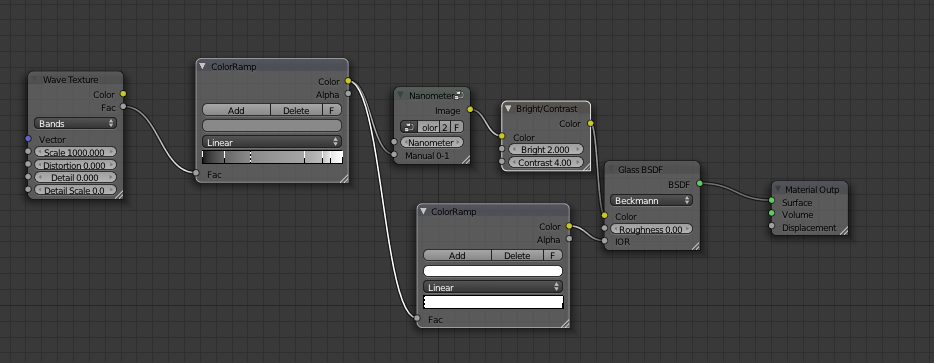
I’m making a super dense wave texture to randomize input spectrum, with values from 0 to 1.
I’m trying to aim for neutral white spectrum with the first color ramp. So that for example there’s more blue and less red.
I’m feeding the randomized and filtered spectrum to both your node group and IOR with colour ramp of desired IOR values (in this case from 1.4 to 1.6 to exaggerate the effect)
Because we’re faking the clear glass by just letting one frequency through at a time, we have to compensate the brightness, so I bumped it with brightness/contrast node.
TADA! Real spectral dispersion. It’s really slow though, that rendered for hours.
That almost looks like something you’d expect from an engine like Maxwell and Luxrender, great work.
Though I’m not sure if the close approximation to actual measurement justifies the huge amount of additional time it takes compared to more simplistic and less accurate methods such as mixing three glass shaders together. Because it looks like the rendertimes would be comparable to Luxrender itself providing you did the same thing there but using just plain pathtracing.
Maybe the new glossy blur option seen in all the new builds will help a bit here, the performance improvements that are also coming may very well help even more and thus make something like this a lot more viable when 2.64 is released.
Try the blend yourself. The node group doesn’t make it much slower, the path tracing does. I bet it’s not that different than the speed of 3-way RGB fake dispersion. Just hoping for bidirectional path tracing for cycles soon.
The hard part is to form the spectrum so that it would form clear glass so that it’s physically correct. Now it most likely over-saturates some wavelengths and darkens the others.
@Qha
Nice Use. Cool to see it already in use (There’s somewhere in Brecht’s Easter Egg Thread a accurate Dispersion Material, just can’t find it (6741 posts and did’nt come up in search…)
@Ace Dragon
What takes long on Qha’s Render are the Caustics, not the Dispersion itself. Which i think (hope) do get some speed up’s in future, since Caustics in Cycles atm are just unusable, unless you Render thousands of Passes.
@ohsnapitsjoel
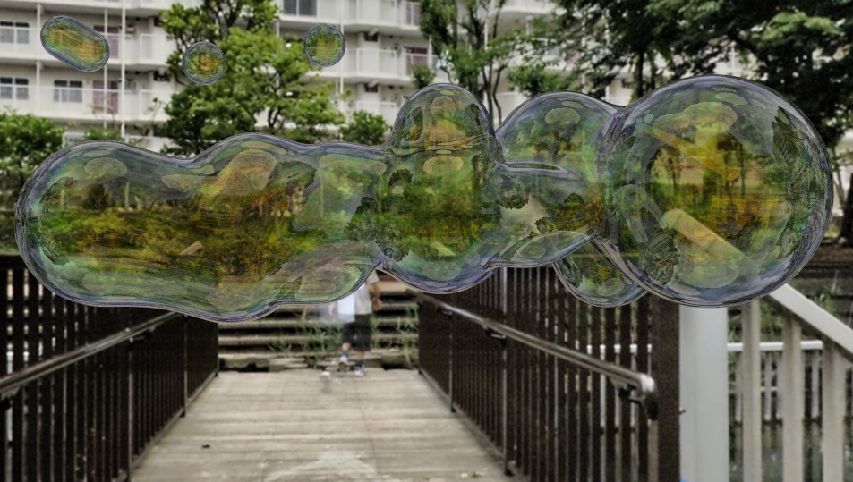
It is actually possible to create more Realistic Soap Bubbles in Cycles. Very interesting btw how Soap Bubbles work: Soap Molecules have one Side which attracts Water the other pushes it away. This way a very thin Water Film builds up the Bubble. Now the interesting Part how the Light reacts inside: Light is reflectet from the Surface and the Second Surface so you get an interference between the two Lightwaves. On very thin Film they cancel each other out and the Bubble appears white, as thicker the Film, the two Lightwaves offset more and can increase or alter the color seen.
@Kemmler
i was able to do something similar as thin film effect. But it does’t take canceling of Wavelength and so into account. As well it’s not really usable cause you have to model the Thin Film, and that need “a lot” of Polygons to look even ok…
I think there is a film option with a nm thickness in LuxRender to simulate that, a film option. Not.sure what materials its available for. nice bubbles though
Considering that Cycles is being developed first and foremost as an animation renderer, I doubt that caustic speedups will be seen in the near feature. That will take a fully-featured bidirectional integrator, which isn’t exactly simple to do. Most people I know who have implemented one can’t even understand what’s going on in their own code when they go back to look at it.


 (appleseed is open-source spectral renderer, NM range definable at compile time. I’m curious about that myself, i’d like to test if it’s possible to Render Infrared, like Infrared photography)
 that would be too cool indeed