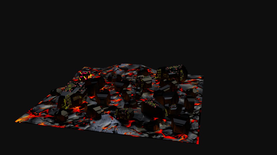
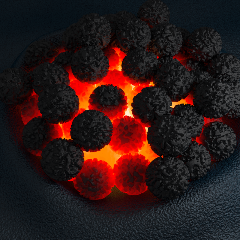
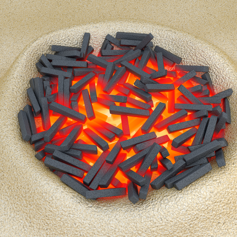
In another thread, RickyBlender asked me if it would be possible to use what I showed to make charcoal for Cycles. I googled some images but, in the end, I decided to make something simple to test my node tree. I just dropped some geometry into a hole in the ground, tuned a bit my node tree and here is what I got:
All the “charcoal bits” were rigid bodies that I joined into a single object with a single material. For some reason, I find it the craziest procedural material I’ve ever created for Cycles. The principle of the “trick” isn’t new but I had never used it this way.
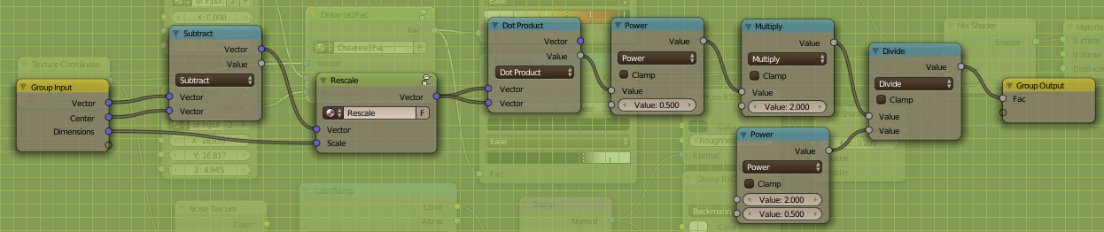
The magic happens in the “Distance2Fac” node group. It calculates a factor based on the distance from the Center and the Dimensions. And that’s all! I use this factor to make the color of the burning bits change from yellow to red thanks to a color ramp. At the same time, this factor is also used in another color ramp to calculate a new factor to switch from the burning material to the non-burning material. Easy as pie!
Very easy: I subtract the Center from the Vector coordinates and I divide each component by its matching dimension (X, Y, Z) in the “Rescale” node group. Then I use the fastest formula I know to calculate the distance (i.e. the length of the vector): sqrt(dot_product(vector, vector)). Multiplied by 2 and divided by sqrt(2)… We got our factor! :eyebrowlift:
I loved the result so much that the blend file is already at BlendSwap, waiting for them to arrive. I’ll post the URL as soon as I’ll get it.
The fake volumetric effect indeed looks quite good, even if the charcoal isn’t yet that convincing and are currently just scaled cubes.
The same thing could be done for anything that has heat flowing out of it, I’m willing to guess you could also use math and texture nodes to introduce some randomization in the mask so as to make it really pop.
I’m talking about Kaluura’s example image, your image is, well, let’s just say that your ability to make shading effects could be greatly helped by learning how to use, create, and manipulate vector data.
Another brilliant and educative Kaluura node screenshot filed away. I have to say I really appreciate that you make your screenshots an easily readable size. Some other very nice materials are posted with screenshots that are just below the legibility threshold and you have to guess at the values…
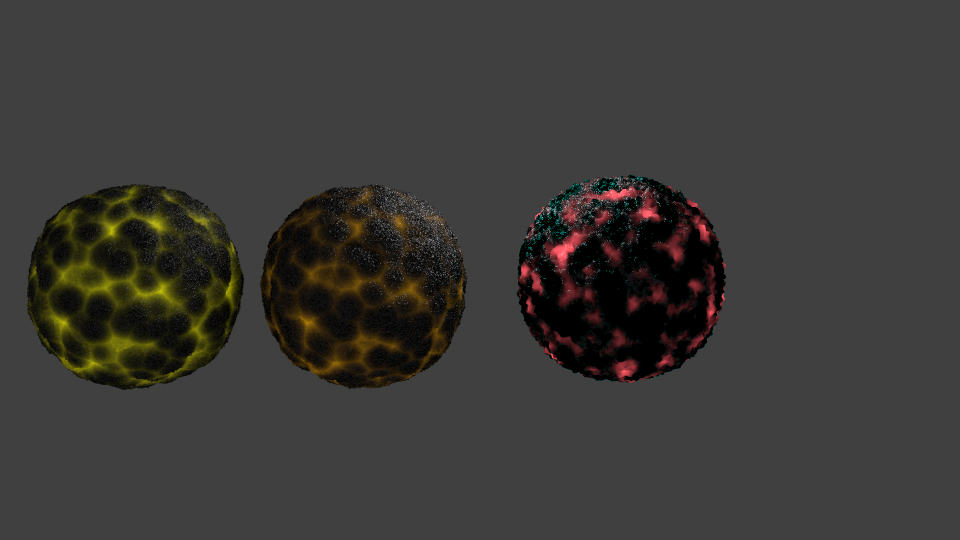
What I did here is however totally overkill. Since a simple bumpmap didn’t provide enough depth, I used a displace modifier… on each sphere. To make the spheres different, I randomized a bit the “Center” so that they are all identical but lit differently. Still, the scene is insanely heavy for a few spheres… altho I didn’t raise the subsurf level higher than 3.
If I had to do it seriously. I’d start from your 3rd sphere (the pinkish one that I like a lot) and I’d use its bump map as factor to drive the 2 color ramps (light color and material switch). If the material is fully procedural, it’s really easy to randomize the noises so that multiple linked copies appear different. (BTW, if you want to show the node tree of the pinkish sphere, nobody would complain.)
@AceDragon: What?! You don’t like my slightly overcooked french fries? Go to MacDonald’s!
Any way… If I weren’t so busy burning my fingers with charcoal, I’d explore the randomization part. There are so many possibilities that I almost don’t know where to start.
@DruBan: You’re welcome. I really don’t like blurry screenshots of node trees either. What’s the point if you can’t read everything? So, I don’t inflict such horrors to others either.
what about using the other nodes set up the one with all the balls
to make some charcoal pieces from several objects may be like you did on other model
beginning to look very nice this is lookng super hot !
Mcdo does not have that !LOL
can you show the nodes set up for the meatbals and the last pic
i d like to modify some of the charcoals on top to give some % with yellow grey or redish color
and set my own shapes too!
may be use some meatbals around
much better then what i’v seen before
dont’ know where you get your inspiration
but it is good
any tips on that ?
@RickyBlender: You’re lucky, I didn’t save what I did for the last image but I could restore the last session… So I can do better than posting snapshots.
your very good with the nodes math
i’m trying to understand on set up which you did i think
and having some difficulties
is it possible to discuss it so i can have a better understanding of the math involve to make it work!
mind you it is not a complicatad one so should be quick i guess
@RickyBlender: I don’t want to sound unpleasant but the node tree in your file is the proof of the Shakespeare’s monkeys theory. Somebody hired an army of monkeys to punch numbers in the node tree until a result happened. Or something like that…
I kinda understand what’s going on in the tree but I don’t understand the numbers. They don’t make sense. Any way…
The goal of the tree is to convert the distance in between the camera and the point of the mesh Cycles is working on into a color. For each R, G and B component, the View Distance is divided by a huge value which give a very dark color… multiplied by a high value to make it super bright… and then mixed with a very dark color to make it more normal. It works but… please!
Using the distance squared changes the curve of response. Instead of linear variation, it gives a curve.
What you did makes sense. To convert (x/A) * B into x * (B/A) should work… but it doesn’t in this tree! Nonsensical! So… I set the tree on fire and I planted a new one.
On the left of the viewport, you see the result of the original node tree and, on the right, what I did. (The colors aren’t exactly the same but it’s just a matter of fixing the color ramp.)
The principle is simple. There’s a little over 50 Blender Units from the camera to behind the red word. Let’s say 60 BU. So, when you divide the View Distance by this value (called Limit in my tree), it gives you a factor from 0 to 1, from the camera to the Limit. We use this factor to drive a color ramp. That’s all. I left the RGB curve but it has no effect. Using the distance squared already produces a curve in the output.
somenone pass me this nightmare !LOL
that’s why i ask you to give me you toughts on it cause it did not make much sense !
i tought why not use the other more smiple function for lightdistance in geometry node !
i could not see why such big numbers where use
but i think now after your comments
you gave it some illogical meaning which is beginning to make sense !LOL
and agree X^2 makes a curvy thing
which could have been done with the power math node
for the camera data
the view distance
this is for the camera itself not the viewport distance to object i assume here!
what is the difference between this and the geometry distance or lightpath dist node ?
also for big number like that what would the clamp do
limit output to 1 ?
ramp node
is there some sort of a math model for this ramp node ?
 The principle of the “trick” isn’t new but I had never used it this way.
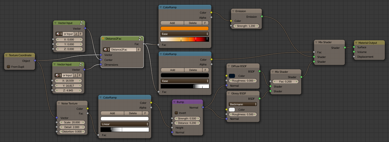
 I’ll post the URL as soon as I’ll get it.