Every inter- or extrapolated point in relation to a given UV triangle is in the mesh face’s plane, that’s right. It’s also true for polygon UVs and mesh faces, as long as they are flat. Otherwise only for triangles.
Every point within a UV face describes a point on the mesh face’s surface. Every point outside describes a point in the same plane, but outside the face’s surface. Note that the UV face must be defined. If the entire UV map contained no overlaps, then any UV coordinate that lies in any of the UV faces will be mappable to a point on the mesh surface, with no ambiguity. With overlaps, there will be multiple solutions, or the UV face you want to calculate the corresponding mesh coordinate for must be specified. Every point outside any UV face will not correspond to a point on the mesh surface (but around or inside the mesh), unless you clamp the UV coordinates to [0, 1] - which will result in texture repetition (as if you were sampling from an endless tile grid of the texture).
-find the face object, get its normal and some kind of relevant coordinates you can use to translate the UV X/Y coords to space
The “relevant coordinates” that can be used to translate UV coordinates to 3d space coordinates are the vertex coordinates of the face/triangle (both, UV and mesh).
-get the scale of the UV map’s coordinates relative to world space coordinates
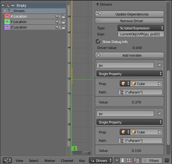
No, you wouldn’t do that. You interpolate the 3d coordinate in object space, then multiply the world matrix by that coordinate to receive world space location.
-find a point(we’ll call it Q)in space described by the UV map’s X/Y coordinates
What? You mean you would scan the mesh until you find the corresponding UV coordinate, only to know that the input 3d coordinate is correct? In the worst cast scenario, that would mean to actually check EVERY 3d coordinate, O(n)-ish. That’s just wrong. You would calculate a single 3d coordinate from the UV coordinate directly, O(1).
-cast a/two rays starting from point Q along the face normal vector, and you should find the equivalent surface point
That assumes that a UV coordinate might not be in the mesh face’s plane. But it can’t.
There’s really no need to construct a plane a do fancy calculations and raycasting. A barycentric transform is all that is needed. It takes two triangles and a point in the first triangle’s plane and calculates the cooresponding point in the second triangle. It can do that with 2 triangles in 3D space. If you want to transform a UV triangle to a mesh triangle, then the former is 2D, whereas the second is 3D. We can put the 2D triangle in 3D however, by assuming z=0:
(0.15, 0.89) –> (0.15, 0.89, 0.0)
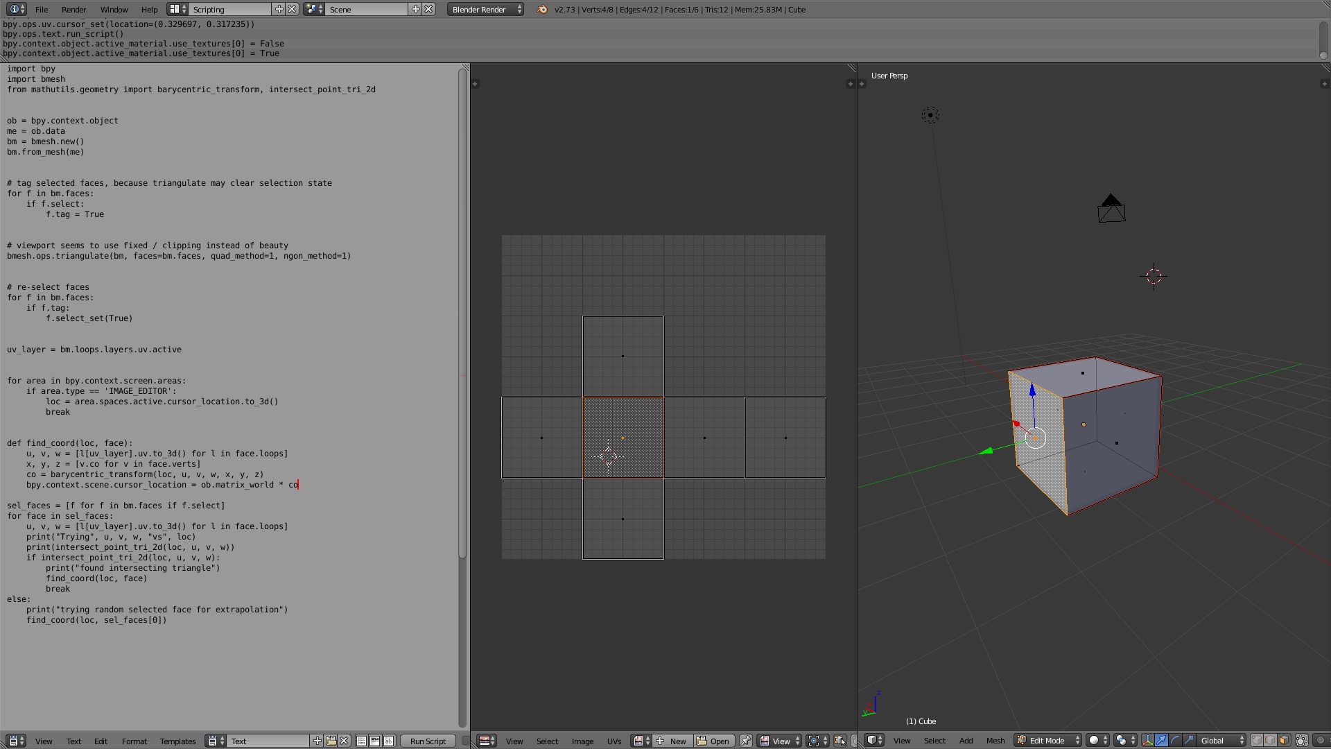
Now that triangle is also 3D and we can transform the point from UV to mesh triangle. That’s what my above code is doing.
In particular, it triangulates a copy of the mesh to allow barycentric transformation, then finds the input UV face that the user must select beforehand (remember, any coordinate in UV space can be transformed, but it may not be on the mesh surface).
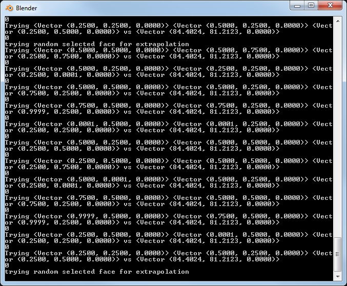
Due to the triangulation, we do not know which triangle is the best option to use as input for the transformation - we potentially want a point on the mesh surface, and thus we need to chose the triangle the user-defined input point lies within. Otherwise we would extrapolate a coordinate, which is an issue if the target mesh face is a non-planar polygons. We would end up with a coordinate not on the surface in that case, it should still work for planar target polygons however. To determine that triangle, the script does triangle-point intersection testing for all triangles the triangulation generated from the input face. If the UV-space point the user wants to calculate the 3d coordinate for isn’t within the selected UV face, no intersection test will return true. The only option is to abort, or use a random triangle to extrapolate a (possibly unwanted) coordinate - my script does the latter.
Then it carries out the barycentric transform by using the user-defined point (2d cursor location), the UV triangle vertex coordinates (remember, to_3d()) and the mesh triangle vertex coordinates (the one that corresponds to the UV triangle, ideally with the point lying within). The resulting mesh coordinate is transformated to world space and the 3D cursor placed at that location.
This is the code of the barycentric transform BTW:
Since our UV triangle is 2D, it should be possible to slightly improve efficiency, because we do not need to “flatten” it. See the comments in above linked code, dimensionality is reduced from 3D to 2D for the input triangle, but not needed in our case because it’s already 2D. This reduction is only possible if the input is planar, which explains why only triangles are accepted - every polygon with a vertex count greater than 3 can be non-planar.

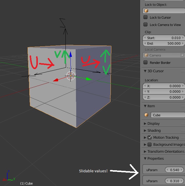
 ) Which means I can possibly use it for rigging, (if I can work around update order stuff,) and try to port my Maya facial scripts (sliding skin for lips etc) over to blender…
  (even though to some degree the ‘shrinkwrap’ stuff might work instead, I prefer more control.)