I am an artist working with a python software developer. We need to create a virtual tape measure for a curved surface.
I have looked at existing scripts that measure straight measurements between two points. Or take the sum total of an edge loop measured in edit mode.
The obstacles I am trying to overcome are:
Measuring the length of an edge loop vertex group, as a sum total of edge length, is only possible in Edit mode. Is there a way to get this information using a script at any time (as part of a larger script that will modify the object)?
As an object changes size, due to a modifier like an Armature stretching the object or a shape key morphing it, the edge measurements are only made permanent when the modifier (or shape key) is applied. Is there a way to gather vertex group measurements without applying these?
Or is there another way to do this that does not involve edit mode and vertex groups?
I was chatting with devs at Makehuman about their built in measuring system. They mentioned they use Numpy and SIMD and provided reference to their code. I’ve passed this on to my developer (as they may understand it) but don’t know if the same method can apply in Blender.
Some things they said were:
“It’s an O(n) operation, with n the number of reference points in the edge loops.”
“Since we simd operate the sum using numpy, its very very low cost.”
“We simply apply the morph at a certain weight and sample, and use an iterative O(lg n) algo.”
So can someone interpret that for me from a Blender point of view?
An alternative method I am considering is to place empties as reference points, constrained to vertex points on the curved object. Then have a script that measures the distance between these empties and sums them up.
Any help or advice you have that I can pass on to my developer is welcomed.
That is what I would like, yes.
I have only referred to it so far as measuring the distance between vertex points and objects, and summing it up, as I did not think there was a way to do what you have illustrated.
Hi batFINGER,
you say add a path. Is there a specific reason that a path is more suitable than a bezier curve or circle? In some cases a circle may be a more appropriate starting shape (to get a full circumference of an irregular shape).
I had tried a similar technique with a circular edge ring as a separate object that would be shrink wrapped and the edge length measured in edit mode (sum total of edge lengths). I did however use the projection option and I think some of the results were inaccurate. A curve does sound like a more efficient solution.
Why do you say you need to apply the scale on the path?
I had a quick look at that other thread. There was your array technique and another one. What is the difference between them? Is the theory behind the array that you are creating a tiny point of measurement and repeating it along the path and then adding them up? Like 0.01mm sections. I’d like to understand a bit more. I like to understand the theory clearly, as I am yet to understand and write Python myself.
I had tried a similar technique with a circular edge ring as a separate object that would be shrink wrapped and the edge length measured in edit mode (sum total of edge lengths). I did however use the projection option and I think some of the results were inaccurate. A curve does sound like a more efficient solution.
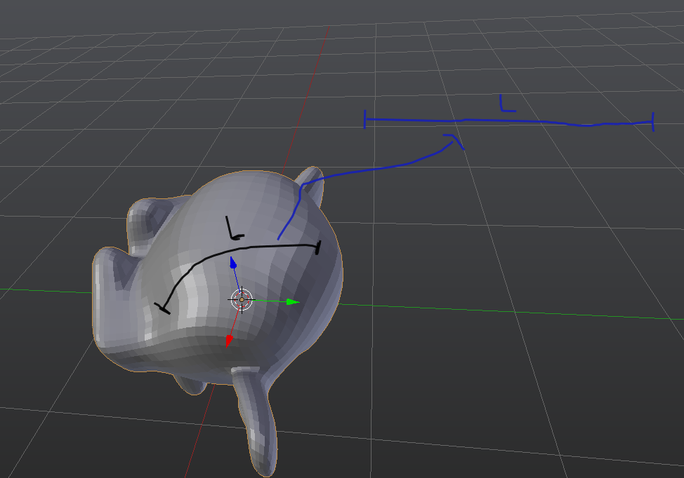
For some reason applying a projected path gives unexpected results. Looks fine as the modifer, completely different curve once applied, A simple path added above a sphere, projected -Z shows this.
Doubt whether the modifier changes the edge lengths in edit mode anyhow.
Why do you say you need to apply the scale on the path?
More important to apply it on the “bit” with array modifier. Applying scale becomes a bit habitual as it is a common source of nonsensical results.
I had a quick look at that other thread. There was your array technique and another one. What is the difference between them? Is the theory behind the array that you are creating a tiny point of measurement and repeating it along the path and then adding them up? Like 0.01mm sections. I’d like to understand a bit more. I like to understand the theory clearly, as I am yet to understand and write Python myself.
The array modifier has a handy “fit curve” option. The length of the curve can be approximated straight off the dimension of the modified “bit”. Try this with a cube and a curve.
Scale the cube down to some precision size you want, and apply scale.
Add an array modifier to the cube with “fit curve” and select your curve as the “curve object to fit array length to”. The default settings of relative x 1.0 of the array modifier will give you an x dimension on the cube that approximates the length of the curve, even as the curve is scaled and edited, but unfortunately not modified using a shrink-wrap modifier.
It makes sense to apply scale to anything scaled in object mode. I often scale in edit mode to ensure I don’t fall for that little issue. So, the “bit” being the object used to measure the length of the curve, may be a default cube that most would just scale down in object mode, therefore scale would need to be applied. I would expect that if the curve had been scaled at any point then it would need to be applied. If neither were scaled in OBJECT mode then you would not need to apply scale.
(Sorry to be long winded there, but I prefer to clarify, rather than assume)
I will try this out. I have seen this modifier in use before but not for this purpose. Smart “outside the box” thinking. You say it will adjust to the length of the curve as it is scaled and edited, but not modified. I gather you mean that is why you have to apply the modifier. Which makes sense, as modifiers are non destructive, and therefore not permanent, until applied. The same goes for shape key morphs. You can always tell when you go into Edit mode as it will revert to the default shape of the object.
I will ask the software dev to have a look at the script once I’ve demonstrated it manually.
Can a script apply the modifier and record the measurement, then undo the ‘apply modifier’? For example, if we were testing different shape changes and have a script run to provide almost real time changes to the results.
Or perhaps duplicate the curve, apply it and measure, record the measurement and delete the curve.
object.to_mesh will give you the obejct as a mesh with all modifiers appllied. However you never have to “see” it in the scene.
So…even if you have a curve with a shrinkwrap modifier.
In the console…with a bezier curve as the active object
remember C is short for bpy.context
my_mesh = C.object.to_mesh(C.scene, True, 'PREVIEW')
mx = my_mesh.matrix_world

L = 0

for i in range(0, len(my_mesh.vertices)-1):
    V = mx * my_mesh.vertices[i+1].co - mx * my_mesh.vertices[i].co
    L += V.length

print(L)
There ya go. Now all you have to do is get your curve object to behave…hint hint…grease pencil and then gpencil to curve + any modifiers.
Alternatively, if your programmer wants to get really fancy, and you are measuring on meshable objects. You can borrow some code from the Contour Tools addon (It’s a paid addon, but it’s open source and free to use) to actually cut across the mesh and not rely on shrinkwrap and stuff. A little more of a headache but it will be the most accurate because it will have a resolution of the underlying mesh, not the sampling of the curve.
Patmo that is exactly what I needed to know.
You are right that I am thinking “make a script duplicate a bunch of user steps to get what I want”.
As a non-coder I am thinking the ‘long way around’ the problem. Once I understand more code I’ll be able to look at the solving issues more directly.
The code you mention here looks to be exactly what I need. From what I can decipher, the script converts to mesh (behind the scenes, non destructively?) then sums up the vertex distances in world units. Is that correct?
I had thought of the Contour Tools addon. Which I have used. Just wasn’t sure if that behaviour it uses was applicable to another purpose (because I don’t know the code possibilities).
I will ask the developer to give it a try and comment here.
Thank you very much.
I will pass that on. Good to know. Did you work on it?
I’m really impressed with Jonathan Williamson’s effort to make a better to through community funding. Strange how a paid plugin can change your point of view.