Took over 400 reference photos of the actual aircraft, slowly building it piece by piece. Should be quite accurate when it’s done. I am looking for any modelling crits from people that are in the know. Eventually it will have D-Day stripes and the whole bit.
I used agisoft photoscan to import the rough scan and all camera positions in blender. I then retopo the entire scan a panel at a time. Some areas have more detail than others. I use the camera positions and reference photos I took of the actual aircraft to fix errors and model details the scan missed. The aircraft is the C-47 out front of Evergreen aviation museum in mcminnvile oregon usa.
However, it seems that you have troubles to obtain the perfect circular cross-section shape of the NACA cowlings.
Am I right, guessing that you split these cowlings into separate panels? And they are smoothed by the subsurf modifier? I would suggest to form them as a single piece (at least: do not cut them along the circle radius). In this way it is easy to obtain a nearly perfect circular cross-section of a subsurfed surface. Then you will create convincing impression of these panels using textures (bump maps, reflectivity map, etc).
[SUB]It is still possible to cut such subsurf-smoothed surfaces along radius, but you have prepare appropriate layout of the mesh before. (To do it, you have to create the root cross-section first, containing a double vertex in the point of the split, and still having a perfect circular shape. Then you can extrude such an edge loop into the shape of NACA cowling. Finally, split this mesh along these double vertices - cutting subsured mesh along topologically “sharp” edges does not alter its shape). Well, these and other methods you can find in my book (its address is at my signature, see below).[/SUB]
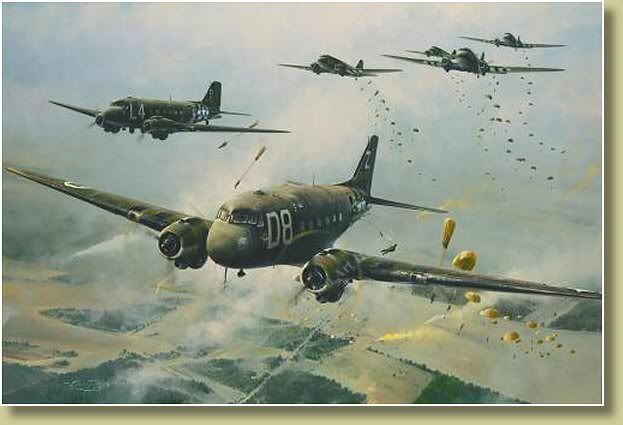
What a historical plane. As a 1950s Airborne Soldier I did not jump the C-47. They had moved on to the C-119, C-123 and C-130. But, many of our older sergeants had jumped it in combat. And, of course the part it played in WWII is legendary. That Skytrain going over England headed for France must have been chilling for those looking up on D-Day.
Thanks for the comments, I’ll try to prove my accuracy with some side by sides soon. I actually don’t have any subsurf applied at all as of yet. I have a workflow I’ve been refining for some time. I’ll elaborate more as I progress.
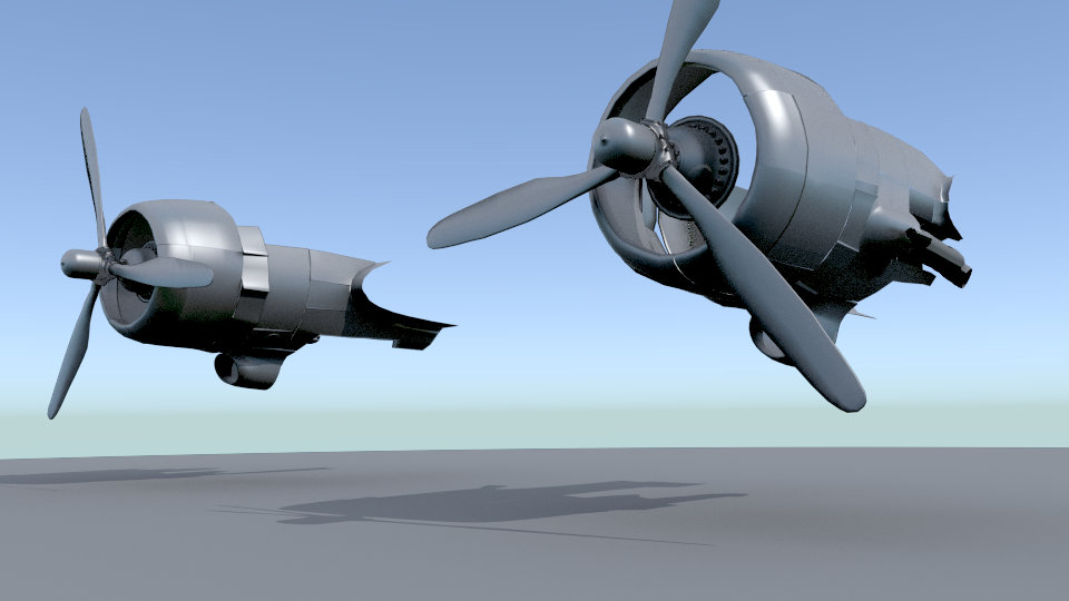
So I’ve been working on the Pratt & Whiney R-1830 Twin Wasp a little along with the variable pitch propellers. I’ll post side by side with the reference photos when I’m a little further along.
Note: I know the propellers are backward on one side, I’m just using the mirror modifier for now, at some point I’ll turn it off and tweak the differences.
Thank you so much for your work, my coworker bought your book and got a lot out of it. I’m experimenting with my own methods which works better in some ways and worse in others. I didn’t realize the cowlings were perfectly round, I’ll tweak them in thanks:)
well more like 2 X 7 = 14 I think
I did a 9 pistons radial engine not easy or low poly to get nice 3D model !
but nice challenge in any case
did not take the time to make this big one
i began doing some of the B-17 B-24 and I might do this engine
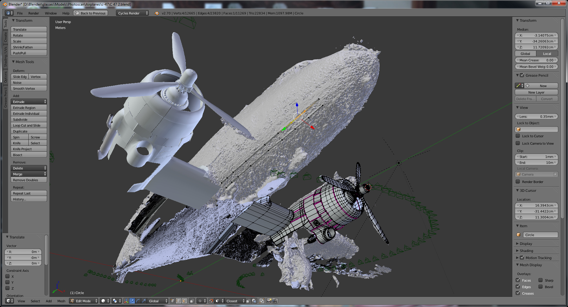
Using the pictures I took of the actual aircraft I converted them into a 3D model using Agisoft photoscan. I then know I have all of the proportions and scale correct. I also have closeup photos of every area of the plane. Here I’m modelling the underside/nose using the workflow
[ATTACH=CONFIG]303980[/ATTACH]
You can also see from the screen shot I have the position of all 400 cameras and their corresponding photos so I can render from the EXACT perspective of the photo and texture paint as well.
A very interesting method! For sure it helps greatly to catch the exact proportions of the modeled object. (For example, in the classic methods it is difficult to determine the exact proportions of the landing gear to the fuselage or wing).
On your picture it seems that this method produces relatively rough reference surface. Relying on this basic data, do not forget about the technological details of this airframe. In the times when it was designed engineers often shaped fuselage or nacelle cross-sections using combination of arcs. I won’t be surprised, if the middle part of this fuselage and the tail has a symmetric cross-section, based on two ellipses.
I’m glad you like the idea, I really respect your effort and attention to detail and your input is GREATLY appreciated:)
All 3D Scans are noisy, this is noisy because the computer is extrapolating the data from the photographs which are blurry etc, it’s actually not as noisy as it looks, the areas of the scan where I had detailed photos are quite acurate. The scan gave me some details of the pistons but not much. I’ll have to model the pistons the old fashioned way… google images. The good news is the scans caught enough of the engine that I’ve got the scale and placement of the pistons, just not the details.
Lots of work to do… but moving along nicely. I have a question… how should I do rivets. I’m considering using hair with object and ‘painting’ them on. Another option is to literally paint them on with bump maps when I’m done. I could use dupliverts as they would be nice to instance… any thoughts?
Personally, I create rivets using bump maps, otherwise it would be too much work. (I have never seen finished model with modeled rivets, although I saw one or two unsuccessfull attempts to do such thing).
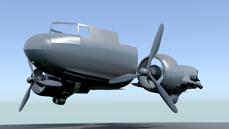
I have impression that the cross section of this fuselage near the wing should be more regular. (Use curves of greater radius, and change it gradually). You have fixed the engine cowlings, but the shadow distribution on their surface reveals that they still do not form a perfect circle. Such problems with regular shapes happens, when you have too many vertices in the mesh (it is difficult to place all of them properly). It looks like a weary skin of a very old plane :).
Unfortunately I’m having trouble getting the right side of the aircraft to compute with my little computer (the file is too huge to add more chunks to the 3d scan model) Also the real problem is I don’t have the center of the aircraft in real world space from the 3d scan and thereby my mirror isn’t accurate. I spent a long time thinking about it and I can’t seem to figure it out. I started writing a python script that would allow you to move the model and then go to edit mode and move the mesh back to it’s original position to allow me to iterate the object center to the correct position/rotation. Anyway my python script wasn’t working too well, so I got frustrated and roughed int he fuselage.
As you can see I just roughed in the fuselage, lots of detail to add. Started the landing gear, kind of all over the place, I tend to model by brush strokes and then refine. I know the leading edge of the tail is messed up. I think I’m going to try painting on the rivets with hair and then baking them to bump if I get into trouble…