Hi all,
I am pretty new here. Well, I have been reading around for some time…
A friend of mine asked me if I could figure out some method to create a tool for her in her artwork visualisation process.
I won’t go into too much detail yet (I will likely post a more specific thread to the project itself soon) as it’s not so relevant to the problem at hand 
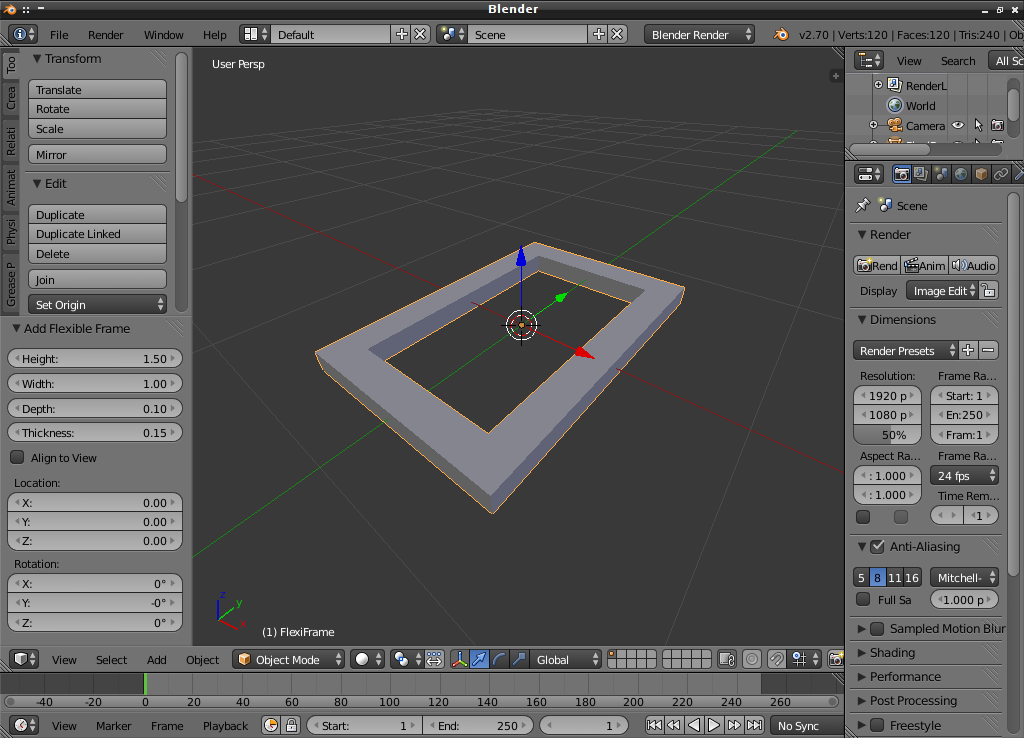
I have used bpy to construct a base for ‘picture frame’ mesh - much like the BeamBuilder (http://wiki.blender.org/index.php/Extensions:2.5/Py/Scripts/Add_Mesh/BeamBuilder) but I use a different process to construct the vertices and faces.
Once the initial mesh was done (consisting of only 16 vertices) I proceeded to calculate a suitable number of cuts (using bisect) to make along x an y to produce more even topology. [Fig. a and b]

I have some code which then selects the edges adjacent to the four inner top vertices [Fig. c]
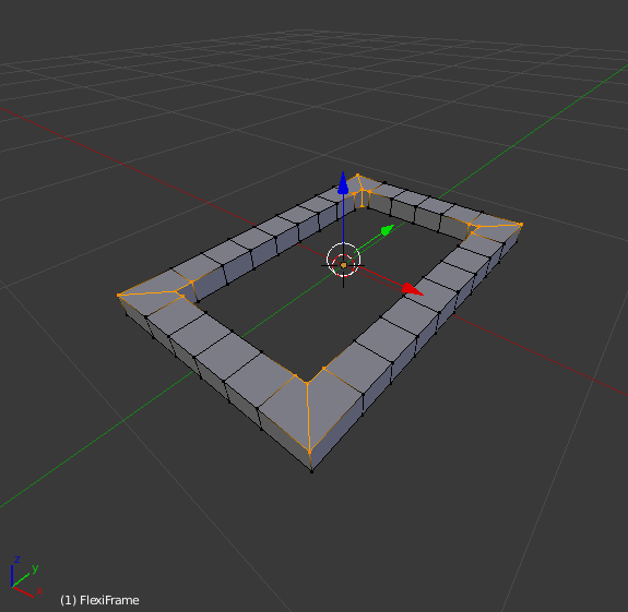
From this selection I am able to figure out which of the edges I need to perform a ‘loop cut and slide’ on, making proximity loops in order to tighten the mesh for the subdivision surface modifier.
Sadly, I am then using hard coded values to determine whether the ‘edge slide’ moves in +ve or -ve edge direction. I believe I can do this as the mesh is always contructed in the same order, but I would prefer a cleaner solution.
Anyway, finally to get to the point at hand. When I do loop cut and slide within the 3d viewport (manually), I am also able to use the keyboard to let ‘edge slide’ know whether the slide should be (E)ven and perhaps (F)lipped. This is perfect as I want the cuts to be evenly distanced each side of the corner edge rings.
However, I can not seem to find a way to do this using python. Is it possible at all - as it appears not to be mentioned in any of the manual or api docs (or other threads)?
I am also wondering if I should research doing all or some of these steps using bmesh instead…
Ultimately, [Fig. d - see next post] is the base mesh I am aiming for (at the moment it appears sufficient). A subd modifier was added with a level of 1, and then applied so I could show the resulting topology.
From here, the front face of the ‘frame’ will be textured separately in order to add ornate detailing with displacement (possibly microdisplacementfrom LuxRender). Is such a mesh suitable for this?
nb. The reason there is more detail in other parts of the mesh is because the ‘frame’ as a whole will also be receiving modifiers in order to bend and twist to some degree.
Hopefully that has provided enough detail for the time being. Let me know if not. As said before, I hope to open a thread for the project as a whole soon, as I suspect there will be a few more hurdles along the way.
Questions, suggestions and constructive criticism always welcome
Kind regards
