I’m currently working on a 2008 Nissan 350Z model. Actually started a thread for this a little over a year ago on the LuxRender forums, decided to carry it over onto here. Went through around 4 different revisions before finally deciding to use a hybrid approach of NURBS and polygon modeling - using NURBS surfaces to flesh out the bulk of the shape, but converting to regular meshes and stitching together afterwards. Whether it’ll be efficient or not remains to be seen but it’s proving to be a working method for the task at hand; I’ve tried making it using only polygons by hand, and while it works, everything came out all bumpy and wrong and not even using the Sculpting toolset would have been enough to resolve it, so I finally settled for this approach.
Eventually I’m seeking to render this in LuxRender as I mentioned (I even have a clay WIP rendering - now outdated), but for now I’m doing tests in Cycles using the PBR custom nodes designed by CynciatPro (great stuff by the way) to get a rough view on how everything is looking. I’m making each component (excluding the various little bits and pieces that hold everything together like bolts and nuts and the like) as separate pieces and combining / merging together when necessary, as well as following actual OEM diagrams to get a rough idea as to the overall appearance of the part.
Before I go too far ahead, what is generally the recommended portions that need to be modeled out? I know in most cases you don’t need to model out the engine block (unless it’s visible then naturally it’s required) as well as some other parts but at the same time I can’t just have empty space where there should be parts in place. I’m just wondering how detailed I need to be so I can tackle everything at my own pace. I have diagrams to help me regardless so it won’t be a big issue if I need to - I’m speaking for the sake of memory usage; I do have 8GB of RAM at my disposal so I have some room if I need it. I also plan on modeling out the interior as well (with working interior lights too, I’m leaving no stone unturned in that regard)
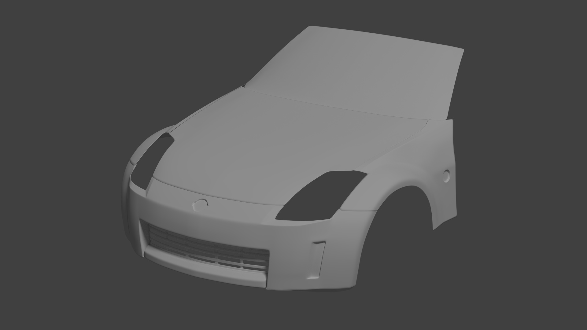
I’ll just work on the body paneling for now and go from there. Currently working on the rest of the windshield in the front and the roof panel.
That sounds like a good plan to me. I like to make the outside first, and then work on the lights, interior, etc. (although I haven’t actually gotten around to doing that yet…)
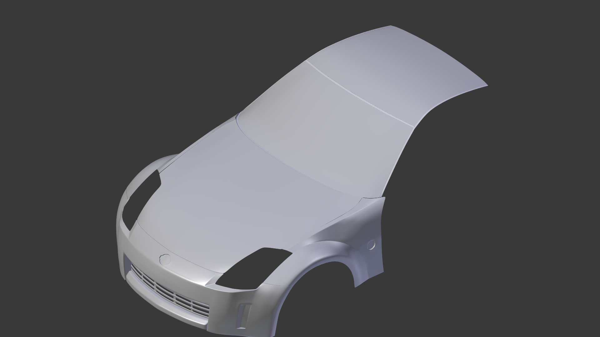
Progress has been slow, but I suppose slow isn’t a bad thing. Lets me think about how to approach the next piece. With that said, I finished the roof panel and a good portion of the insulation that separates out the front end pieces (hood, windshield, etc.) - the rubberized portions in between certain parts of the vehicle.
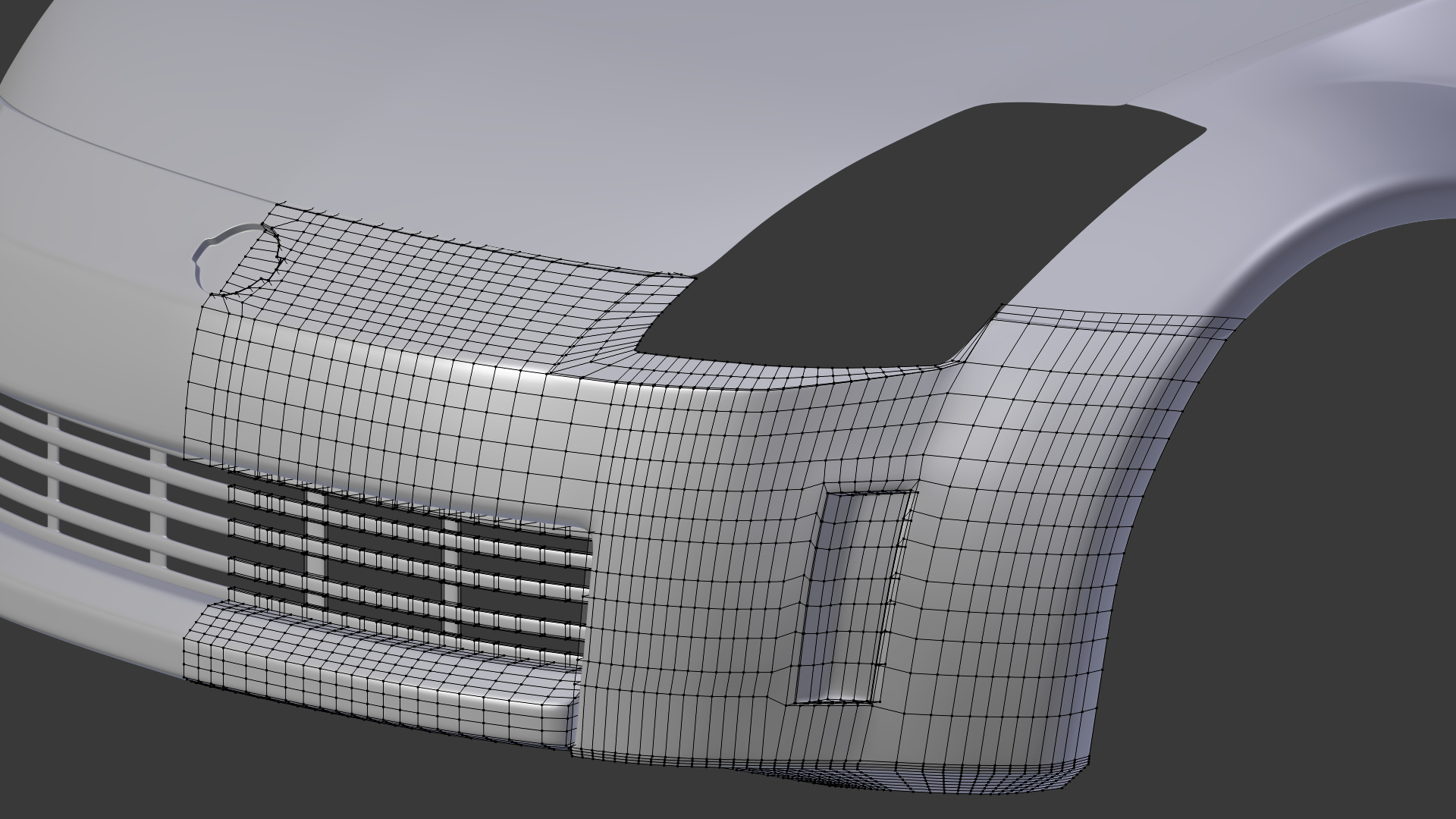
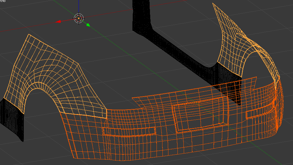
Also included a viewport image of the topology for the front bumper, to show how it looks. I’m wondering if it’s too high-poly (I’m not making this for an animation - purely for still images, so ultimately poly count isn’t a concern)
Yes, that is very, very high poly. Cut the polycount way down by selecting unnecessary edge loops and pressing X > Edge Loop. (If you first switch to “edge select mode” instead of “vertex select mode”, you can delete many edge loops at once.) Then add a Subdivision Surface modifier instead.
Effectively, a bit high poly for this stade, if you need then to make some correction, it can give you soome trouble, a lot of unnecessary works. Imagine trying to reconnect so many vertices if you redo a complete zone. many time lost.
Thanks for the replies, and I guess I should’ve known lol
As it was I had a difficult time lining up the corner of the insulation at the hood so I’m sure the topology played a factor. I went ahead and got rid of every other edge loop in the tightly packed areas so I can keep a nice and consistent flow through the mesh, but also reducing the vertex count. Looks better too. Good call
I should probably reduce the NURBS resolution down to approximately 2 or 3 for now on instead of 4 (which I have been using this entire time) Hopefully the body creation will go smoother now.
Just finished creating the lower portions of the side and started work on the rear fender; that part is particularly interesting to set up because while it’s a bowed out curve, it has a distinct section where it follows the straight line of the side, which I’m trying to incorporate. And considering I’m using NURBS to set up the bulk of the mesh, it’s proving rather difficult.
My workflow is this:
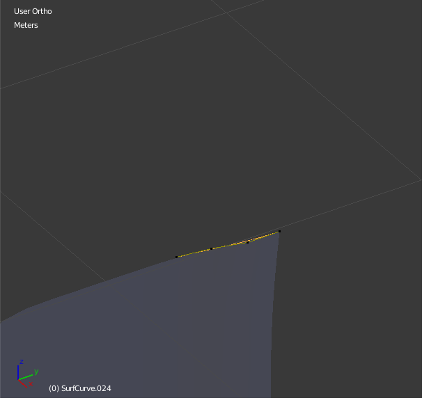
I create (or duplicate) a NURBS Surface object; I only needed to create one initially, and now I’m duplicating certain pieces of the splines and making them their own objects to get the shapes that I need.
Extruding out according to the blueprints I’m using as a in-program guide as well as diagrams that I’m using for a more technical reference, I make my shapes while trying to make sure that the actual mesh being calculated follows the lines.
Before duplicating the object and moving it to my main construction layer, I check the settings to make sure the resolution and order values are sufficient - now I’m using order values of 4 and resolution values of either 2 or 3 - I can always remove edge loops if I need to.
Once moved to my main construction layer, I then convert it to a regular mesh and then either leave it as is or start joining together another piece that it is associated with - I’m essentially combining NURBS surfaces together in regular polygon modes using Merge tools and making minor adjustments with either Proportional Editing or (if the surface is bumpy for some reason) the Smooth brush in Sculpting mode.
It’s a shame Blender’s NURBS functionality is rather lacking but at the same time, the ability to move control vertices and points so easily is a bonus. I’ve tried using NURBS in Rhinoceros 5 and, while VERY powerful, moving around certain parts got rather tedious, especially when making simple adjustments. This current workflow is satisfying my needs though.
Now I’m looking at finishing the rear fender and possibly the rear bumper. We’ll see how it goes.
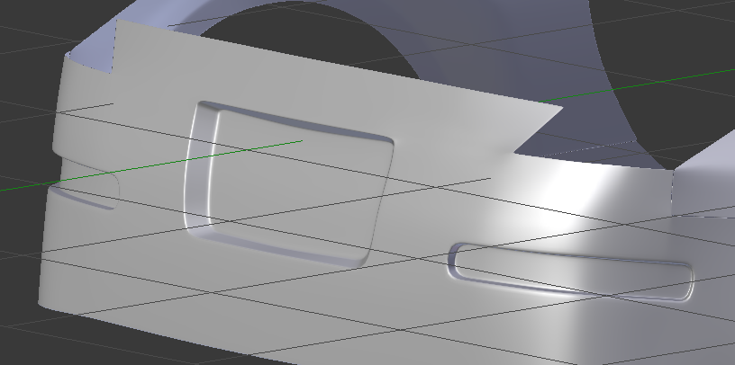
Finished (for now maybe) the rear fender and the majority of the rear bumper. Adding in the right creases for the edges of each piece was proving to be a pain, maybe I should use edge creases instead of edge loops. Also added in the indentations for the license plate and the rear directional lights / reflectors.
My only problem here is the corner where the fender and bumper meets and forms the corner of the rear light - looks like the reflections don’t match up in the regular Solid view, but I put a MatCap to it and it looks fine. I’m wondering if I should join the two meshes, join them, and then separate them again after I bevel that particular edge. What do you guys think?
Arghh lol sometimes I wonder just what I’m doing with my workflow, but now that I’m at this point, and starting to really look at how it’s looking, I have to say… I’m becoming less happy with the way the edges are forming. And plus also the amount of vertices that I have to use to form the mesh, I must admit, is too much to be practical. I’m considering tackling it all over again from a different angle.
Let’s not even mention where to begin with the interior portions once everything is set on the outside; I’ve got a few ideas but I’m not sure how well they will work. I’ll update this again when I reach a similar point to where I was last, but hopefully with a better result.
I suppose this is the price I have to pay for trying to experiment. Oh well. I know one thing, I will finish this, no question. Just needs some time and patience, like everything else. Bear with me, I’ve not stopped working on this.
Not to worry, after putting some thought and brainstorming, I’ve decided to tackle it again, using a different approach following the example set from Ali Ismail in his “Modeling Cars in Polygons” tutorial here. (Note: His work is under the Creative Commons Attribution-NonCommercial 4.0 International License)
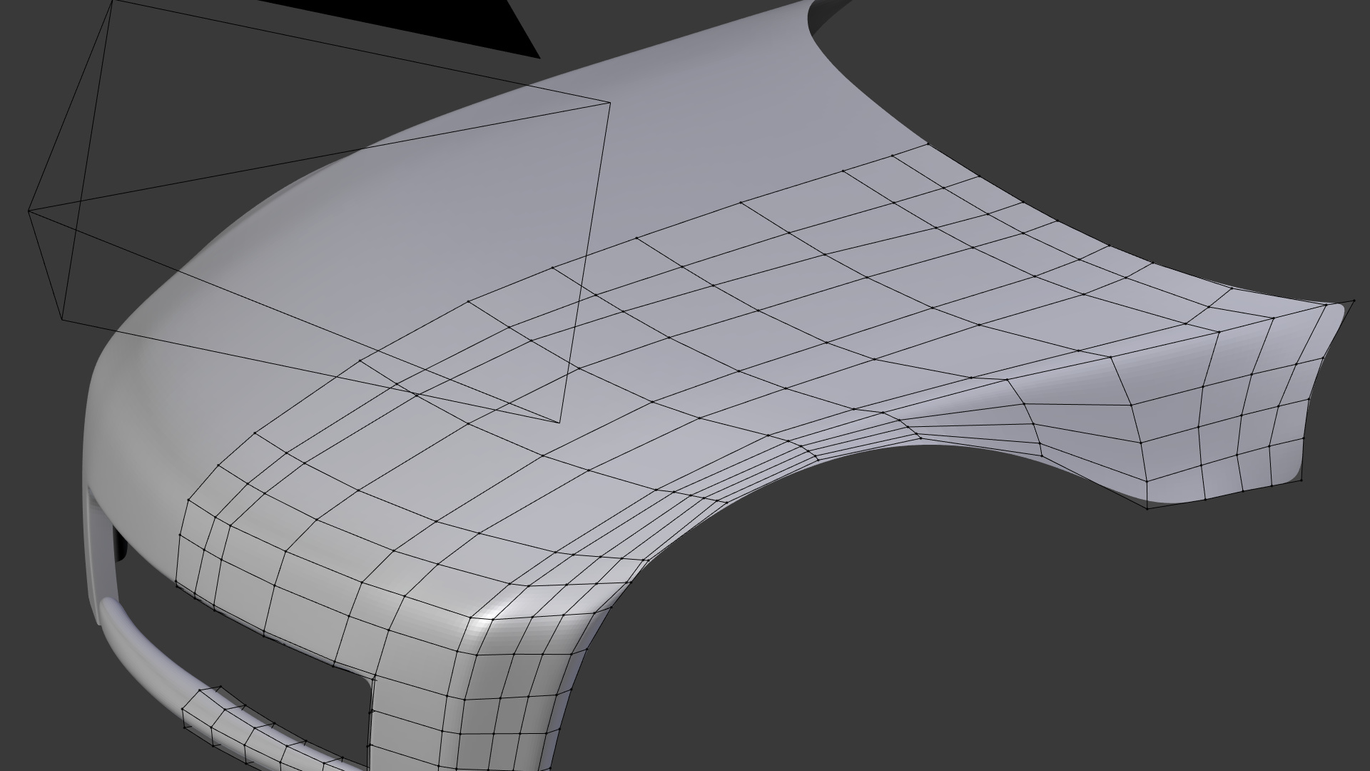
Instead of making each piece all pre-cut with the necessary holes already in place, I’m just going to make it basically one giant piece and, after applying a decent subdivision, create the holes and extra details. Should’ve done this from the start but I wanted to experiment lol
I’m also using Crouch’s amazing F2 addon with this - quite the lifesaver. Lets me set up the boundary edges when I plan to add in faces and rapidly fill them in while preserving the contours.
Above is current progress - kind of concerned over the area near what is going to be the wheel well + front fender as far as poly count. Then again, I don’t intend for this to be a game asset either so that isn’t an issue of mine.