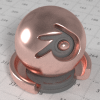
UPDATE: Cycles PBR metals, based on complex refractive index

UPDATE: I have merged this metal shader with my thin film interference shader. Please see this post for all included materials and some possibilities: https://blenderartists.org/forum/showthread.php?403299-UPDATE-Cycles-PBR-thin-film-interference-and-metals

Hey all,

After all the recent flood of PBR tutorials, I thought I’d try my hand at making a metal shader that would

  1. render the correct color
  2. render the correct Fresnel behavior

all based on the complex refractive index n+i*k. Essentially all color and Fresnel information is contained into these two numbers for a given wavelength. For many materials the n,k values can be found at the well-known refractiveindex.info web site, so this shader might be an alternative for rendering realistic metals and semiconductors.

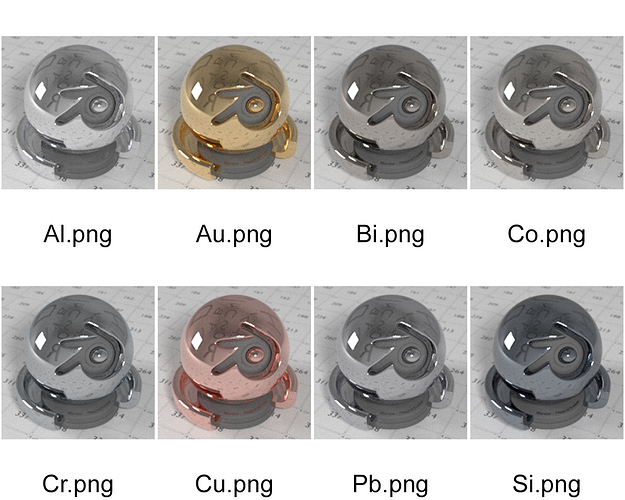
I was planning to make a node group from scratch, but I had a look at Blender’s source code tree and I found an OSL function called fresnel_conductor, which triggered my curiosity. Not so long story short: what I wanted to make was already there in OSL (but it should be easy to recreate the OSL shader with ordinary nodes). I’ve taken the n,k values for red, green and blue* and plugged those into an OSL script for various metals. The results are shown in the image below. Note that I never defined a color anywhere, it’s all just the fresnel equations at work**. Also, when zoomed in onto the edges, a color gradient is visible (especially for the tinted metals), which seems to indicate that it works as expected. I also provide the .blend file with the OSL script link removed, outdated!


If anyone wants to re-implement this in plain Blender nodes, the contents of the fresnel_conductor equation are (source https://git.blender.org/gitweb/gitweb.cgi/cycles.git/blob_plain/refs/heads/master:/src/kernel/shaders/node_fresnel.h):


color fresnel_conductor(float cosi, color eta, color k)
{
    color cosi2 = color(cosi * cosi);
    color one = color(1, 1, 1);
    color tmp_f = eta * eta + k * k;
    color tmp = tmp_f * cosi2;
    color Rparl2 = (tmp - (2.0 * eta * cosi) + one) /
                   (tmp + (2.0 * eta * cosi) + one);
    color Rperp2 = (tmp_f - (2.0 * eta * cosi) + cosi2) /
                   (tmp_f + (2.0 * eta * cosi) + cosi2);
    return (Rparl2 + Rperp2) * 0.5;
}

I hacked in the lesser influence of the Fresnel effect with increasing roughness, as I have no clue what it should be to be accurate. Right now, at a roughness of 0.0 I take the physically correct Fresnel behavior. At a roughness of 1.0, I take the Fresnel value of 45° and apply it everywhere, regardless the angle of incidence of the light. The reasoning behind this is that we might see some kind of angular average (big question mark). For roughness values in between, I interpolate between these two extreme cases.

Edit: It seems that to implement Fresnel with rough surfaces properly you need to have access to the microfacet distributions of normals. Cycles / OSL doesn’t provide for this, so a physically correct implementation isn’t possible without implementing a microfacet surface shader first. The upcoming patch by Lukas Stockner mentioned below will take care of this by implementing a new surface shader type, with surface roughness weighted by the Fresnel coefficient.

Here’s the OSL code:


#include "stdosl.h"
#include "node_fresnel.h"

shader node_fresnel(
    color n = color(0.2),
    color k = color(3),
    normal Normal = N,
    float roughness = 0,
    output color Fac = color(0.0))
{
    float cosi = dot(I, Normal);
    Fac = fresnel_conductor(cosi, n, k);
      color Fac2 = fresnel_conductor(0.707, n, k);
    Fac = (1-roughness)*Fac+roughness*Fac2;
}

Finally, I didn’t check the render speed compared to other solutions like for example using RGB curves (found here: https://blenderartists.org/forum/showthread.php?361151-Cycles-Materials-RGB-Curves-and-PBR-rendering-UPDATED) Interpolating over the angle might be faster than doing the angle-dependent calculation over and over. On the other hand, with this solution there is no interpolation over the angle, and it’s less work to set up a new material (fill in 6 values). Anyway, I hope it’s useful to someone.

*I took the n,k values at the wavelength of 650 nm ®, 532 nm (G) and 450 nm (B). I think it would be best to do a spectral average of the primary colors of blender, but I have no idea what wavelengths these correspond to.
** I didn’t check the correctness of the equations
found it
you can change the glossy roughness in last node

cause as it is they are mirror like glossy
which is way too much !

and with OSL it is always slower then other renderer

thanks for sharing
happy bl

Granted, and it’s not compatible with GPU computing this way. But even regardless the OSL issues, the interpolation trick as a function of angle in the thread that I mentioned in the first post might be faster.
Cheers!

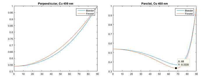
So I decided to compare the results from the built-in OSL shader with the result of the Fresnel equations. Turns out that the built-in OSL shader isn’t entirely correct**. For copper at a wavelength of 450 nm, I plotted the reflectance as a function of angle for the OSL shader and for the Fresnel equations. As you can see in the graphs, they’re not entirely the same. As far as I have researched the issue, this is about the worse case, that is, it deviates most heavily for colored metals in the part of the spectrum that gets absorbed (here blue, 450 nm).


The question of course is, does it matter? Only one way to find out, so I implemented the Fresnel equations in OSL using complex math (meaning with the imaginary unit) to see if more accurate is more realistic. As complex numbers seem to be unsupported in OSL (I am wondering if I’m missing something?), I created a small library to work with these numbers. Anyway, to test I rendered a larger version of the copper metal, with my own shader and the built-in OSL shader. Here is the comparison:


If you look very closely, there is a minute difference visible. But, in hindsight, the differences probably weren’t worth all the work. But now I know :slight_smile:

Nevertheless, maybe the implementation, or even the use of complex numbers, might be interesting to someone so I’ll add the file here: https://dl.dropboxusercontent.com/u/5326890/metals_nk_correct.blend

Here’s the OSL code (also included in the blend file)


#include "stdosl.h"

struct complex {
        color r;
        color i;
  };


shader node_fresnel(
    color n = color(0.2),
    color k = color(3),
    normal Normal = N,
    float roughness = 0 [[float min = 0, float max = 1]],
    output color Fac = color(0.0))
{
       
    void cmult(complex x, complex y, output complex z)
    {

      z.r = x.r*y.r-x.i*y.i;
      z.i = x.r*y.i + x.i*y.r;

    }
    
    void cdiv(complex x, complex y, output complex z)
    {
 
      complex ystar;
      ystar.r = y.r;
      ystar.i = -y.i;
      
      cmult(x,ystar,z); 
      z.r = z.r/color((y.r*y.r+y.i*y.i));
      z.i = z.i/color((y.r*y.r+y.i*y.i));

    }
    
    void cadd(complex x, complex y, output complex z)
    {
  
      z.r = x.r + y.r;
      z.i = x.i + y.i;

    }
    
    void csqrt(complex x, output complex z)
    {
   
      color r = sqrt(sqrt(color(x.r*x.r) + color(x.i*x.i)));
      color phi = atan2(x.i,x.r)/2;
      
      z.r = r*cos(phi);
      z.i = r*sin(phi);

    }    
              
    void RperpRpar(complex cosi, complex n2, output color Rperp, output color Rpar)
    {    
        complex one;
        one.r = color(1); one.i = color(0);
        
        complex m_one;
        m_one.r = color(-1); m_one.i = color(0);

        complex sini; complex z;
        cmult(cosi,cosi,z); //cosi^2
        cmult(m_one,z,z);   //-cosi^2
        cadd(one,z,z);      //1-cosi^2
        csqrt(z,sini);      //sqrt(1-cosi^2) 
        
          
        complex root;
        
        cdiv(one,n2,z);     // 1/n2
        cmult(z,sini,z);    // 1/n2*sini
        cmult(z,z,z);       // (1/n2*sini)^2
        cmult(m_one,z,z);   // -(1/n2*sini)^2
        cadd(one,z,z);      // 1-(1/n2*sini)^2
        csqrt(z,root);      // sqrt(1-(1/n2*sini)^2)
                  
        complex n2cosi;
        cmult(n2,cosi, n2cosi); //n2*cosi
        
        complex n2root;
        cmult(n2,root, n2root); //n2*sqrt(1-(1/n2*sini)^2)
        
        complex Ns;
        cmult(n2root,m_one,z);
        cadd(cosi,z,Ns);        // cosi - n2*sqrt(1-(1/n2*sini)^2)
        
        complex Ds;
        cadd(cosi,n2root, Ds);  // cosi + n2*sqrt(1-(1/n2*sini)^2)
        
        complex rs;
        cdiv(Ns,Ds,rs);         // (cosi - n2*sqrt(1-(1/n2*sini)^2)) / 
                                // (cosi + n2*sqrt(1-(1/n2*sini)^2))
        Rperp = color(rs.r*rs.r) + color(rs.i*rs.i);
        
        cmult(n2cosi,m_one,z);  // -n2 * cosi
        
        complex Np;
        cadd(root,z, Np);       // sqrt(1-(1/n2*sini)^2) - n2 * cosi
        
        complex Dp;
        cadd(root,n2cosi,Dp);   // sqrt(1-(1/n2*sini)^2) + n2 * cosi
        
        complex rp;
        cdiv(Np,Dp,rp);         // (sqrt(1-(1/n2*sini)^2) - n2 * cosi) /
                                // (sqrt(1-(1/n2*sini)^2) + n2 * cosi)
        
        Rpar = color(rp.r*rp.r) + color(rp.i*rp.i);
    }
    
    complex cosi;
    cosi.r = color(dot(I, Normal)); cosi.i = color(0);
    
    complex n2;
    n2.r = n;    n2.i = k;
    
    color Rperp; color Rpar;
    
    RperpRpar(cosi, n2,  Rperp, Rpar);
    

    Fac = (Rpar+Rperp)*0.5;
    
    if (roughness > 0)
    {
      complex avg_angle;
      avg_angle.r = 0.707; avg_angle.i = 0;
      
      RperpRpar(avg_angle,n2,Rperp,Rpar);
      Fac = mix((Rpar+Rperp)*0.5, Fac,roughness);
    }
    
    
}


**assuming I didn’t add any extra bugs.

did you test with different roughness and may be using the new glossy option ?

still uncertain how close you can approximate the colors in cycles!

happy cl

I’m not sure what you mean with “the new glossy option”?

I didn’t test different roughness settings. The Fresnel equations assume a perfectly polished surface, so a roughness setting of 0.0 is fair to compare implementations of the Fresnel effect, I would say.

I think the color accuracy could be improved if

  1. cycles would support spectral rendering (not going to happen soon, I guess), or
  2. A spectral average of n and k values for each of cycles’ primary colors would be calculated. Now I just took the n,k values at 3 wavelengths that happen to be red, green and blue, without knowing if it’s close to cycles’ R, G and B.

is not there a way to calculate the right color equivalent for the N , K values ?

for mirror metal agreed but what happen if you have some doll metal
or like aluminium oxidize ?
need more roughness

and the new glossy option seem to work better for middle Fresnel if I remember correctly
but not for mirror glossy

thanks
happy cl

The whole issue on trying to accurately render metals should be largely eliminated if this patch by Lukas Stockner gets committed.
https://developer.blender.org/D2003

It even uses the multiscatter GGX so it should have perfect energy conservation.

but is it able to do doll metal or only mirror metal ?

I like mirror metal but there is a lot more metallic look then mirror

and will this be added in 2.78 ?

thanks for the tip
happy cl

@RickyBlender:
Yes, with the n and k you can calculate the exact spectrum of the reflected light if you know the spectrum of the light that hits the metal. Essentially that is what the shader is doing, only point is that I don’t know the spectrum of blender’s R, G and B components, so I guessed some values.

Oxidized metals have different values for n and k compared to pure metals. If you have the right values of n and k for the oxides, the color will look like oxidized metal, as long as the Fresnel equations are valid for the type of surface of the oxide (it still has to be smooth). If you want to include roughness you can increase the roughness value of the shader. I only rendered perfectly smooth metals as I want to compare with the Fresnel equations, but there’s a roughness setting you can use. An example is this, with a roughness of 0.05:

I am sorry but I have no idea what you mean with ‘the new glossy option’

@Ace Dragon
Interesting! He probably thought more about the roughness vs Fresnel than I have :slight_smile: Part of the patch seems to take the same approach as I have, with the 3 pairs of n and k values. I’m gonna have a look at the implementation (Edit: the patch uses the exact same Fresnel implementation as the OSL version to calculate the color, which seems to be off by a negligible amount from the true Fresnel result. Also means that the n,k values I looked up for the metals in my shader can be reused).

Cheers!

Lovely, thanks.

I suppose what Ricky meant with ‘the new glossy option’ is multiscatter GGX. As Ace mentioned:"… it should have perfect energy conservation."

just found the link for test on this multiscatter GGX

see test

but if the new Metal node already has it
that would be great indeed

happy cl

I suspect Ricky is talking about the new multiscattered GGX option coming in 2.78. It eliminates energy loss at medium to high roughness values in the glossy, anisotropic and glass shaders.

Ah, now I get it! Thanks for the explanation.

Well, my OSL script just calculates a color (or more accurately a specularly reflected intensity per color [R,G,B]), and you can use any glossy shader that you’d like to use as a metal, including any upcoming improved versions. If you open the group in my blend file, you can see the OSL script connected to a standard GGX metal shader.

If you want to go crazy, hook it up to diffuse or glass shader instead :wink:

Cheers!

I thought the upcoming metallic shader supported both nk based and artistic friendly coloring (as well as proper roughness handling)?

Yes, apparently so. I didn’t know about the existence of that patch when I developed my shader. If you want to nitpick, you could argue that that implementation is slightly off (see curves above), but my own trials seem to indicate that the difference is negligible in practice. However, I now also have a shader to simulate thin film interference (for example, soap bubbles). Example and blend file coming soon! :slight_smile:

You and Secrop need to have a chat :smiley:

Honestly, can you guys all get together and produce a YouTube “PBR for dummies” explanation of this. I’m a clever bloke (IQ 147), and I did grade A Chemistry and Physics at school, 35 years ago. It would be nice to be brought up to date on this stuff.

Andrew Price has this two-part video tutorials on PBR (blenderguru.com), but with that IQ it might be too much ‘for dummies’ :wink:
In that case, start here: https://en.wikipedia.org/wiki/Fresnel_equations and here https://en.wikipedia.org/wiki/Mathematical_descriptions_of_opacity

Cheers!

I posted the v1 with some examples here: https://blenderartists.org/forum/showthread.php?403299-Cycles-PBR-thin-film-interference-(with-blend-file)

Cheers