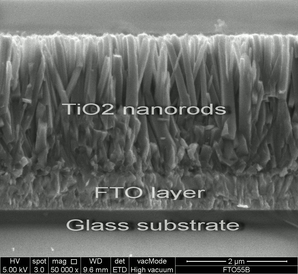
Let me give a brief introduction about my work, I’m a researcher who currently working on photoactive material TiO[SUB]2[/SUB] tinted FTO (Fluorine doped Tin Oxide) glass substrate to act as a photoelectrochemical cell device. As such, publishing our research work in high impact factor research journal is our main task. Therefore, in order to enhance the graphical effect of our research with the aim to ease the reader’s and other research community it is therefore of priority for us to use powerful software such as Blender to achieve our need.
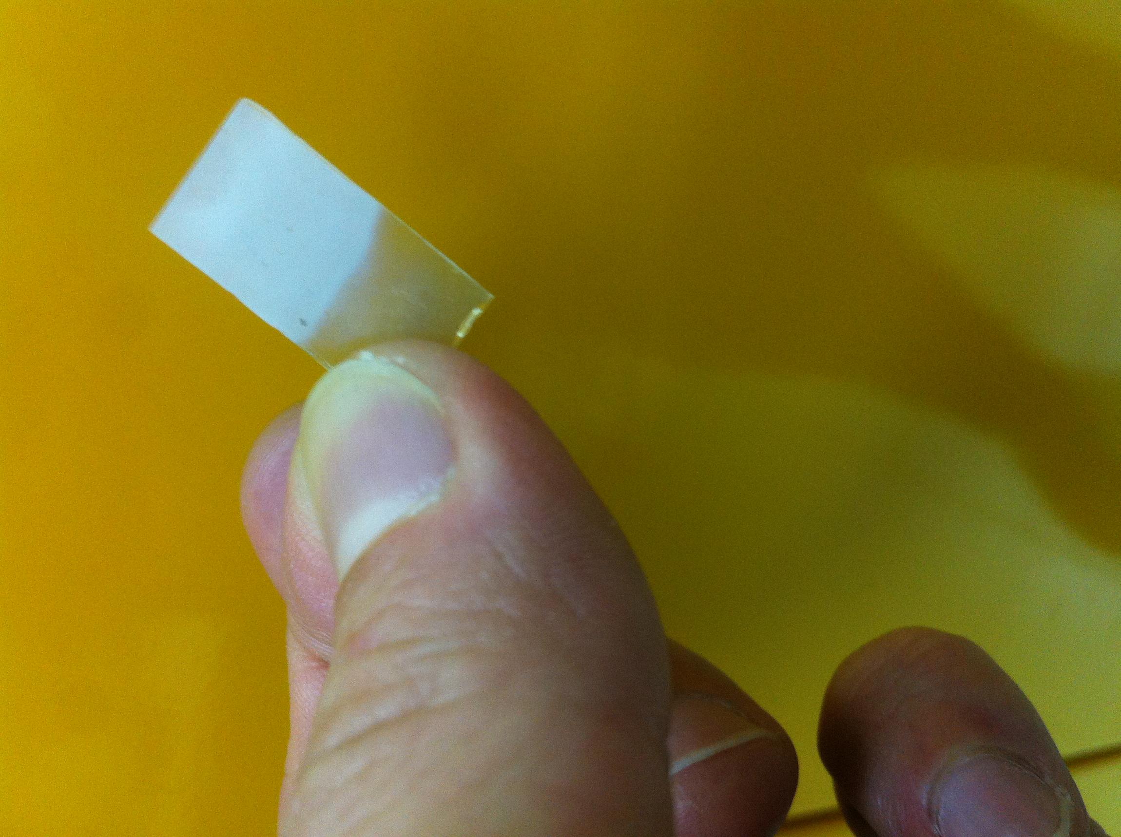
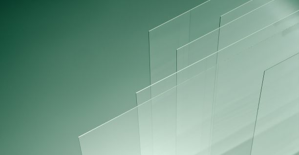
Here, I am struggling to construct a graphical picture to represent my work and below attached files are the pictures captured meant for this post. I want to create a realistic glass effect with suitable lighting effect for the work. My main doubt is how to create a coating layer on top of a plate glass (rectangular in shape) which as an active region to absorb light on the conducting glass.
1)Is anyone can assist me to create such effect with suitable setting? What are the materials setting for the glass and frosted effect (TiO[SUB]2[/SUB]) on the glass?
How to create a realistic effect of interface layers of TiO[SUB]2 [/SUB]and glass? I have enclosed some pictures to represent the need of my work.
Thank you and look forward to receiving any input from you guy soon.
Videos would be better than images in this case. Although I’m not 100% sure what you are trying to do - an accurate representation I don’t think is possible, but a visual fake representation might be doable - I would try something like this:
Make custom glass shader based on glossy and refraction, now you can control some sort of coating effect (less transparent, more transparent) changing reflective and refractive color. Independent roughness control would also be present. Frosting is currently problematic, but someone here has a fix for it or alternatively it should be fixed in the next version (no darkening).
Basically, you can’t use Blender to create a physically based coating of controlled thickness, but rather approach it with a fake “what you can see” approach. For the real deal, I think you’d have to use some sort of optical simulation software.
Also, how the heck are you handling fluorine? That stuff is nasty
Not sure if it’s what you mean, but maybe my thin-film interference OSL shader can help you achieve the look you want for the interface layers? It’s single-layer only right now, though. But I agree with CarlG that it might be simpler and give better result by faking it, for example change the color of the reflection as a function of angle with the fresnel node.
@prutser: I have tried your using your blender file and mimic the setting that you’ve made. However, I couldn’t find “fresnel interference” mode under in Add tab (node editor)… Anyway of finding it?
@burnin: Thanks pal. Yes I do have the FESEM image but I want to show the photographic scale only. The formed TiO2 is a array of nanorods. Let me enclose the file as attached file and you may have a look.
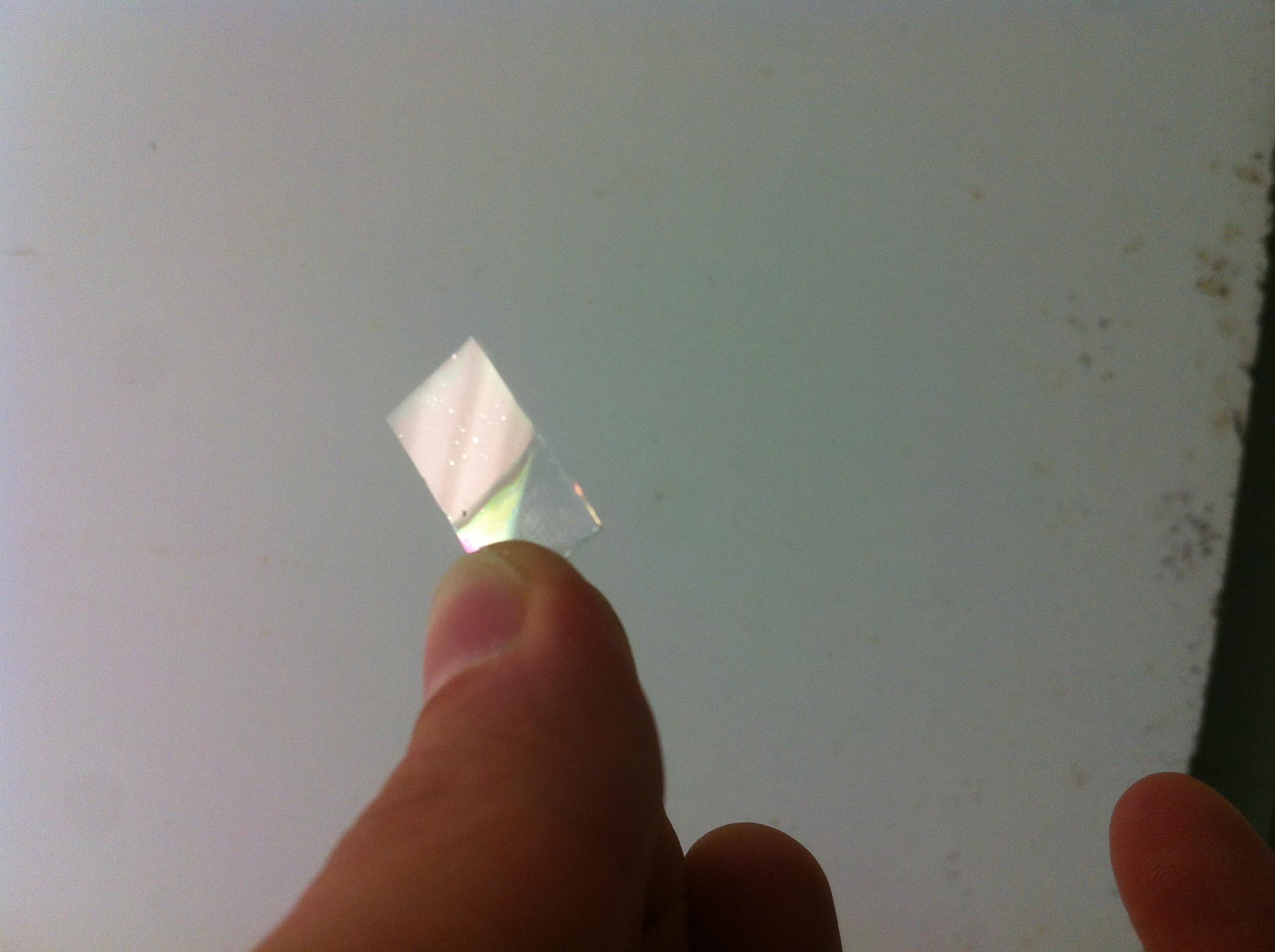
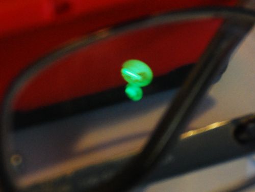
The “usual” observation (at least in my own coated glasses) is variance on the reflective part. For this, and if this is what you want to achieve visually, just create a custom glass (refraction and glossy) driven with fresnel. The white reflection should then be slightly green for facing angles changing to white at glancing angles, again using fresnel or facing. This green tint at facing angles clearly visible on my glasses is a result of anti reflective coating.
Facing reflection tints green:
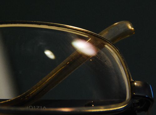
At more glancing angle goes to white:
If you’re able to hold sample in hands, make your own observations as to what is going on at varying angles. The shot above (sorry for shaky hands and out of focus, lol) is a white light (auto WB, but outdoors is tinted blue so I guess indoor WB).
Sorry, I didn’t get the forum notification much sooner. I’m also not sure what you mean with your question. Did you try the supplied blend file? But anyway, I agree with CarlG that faking it is a much better solution if it gives you the look you desire, and I think his suggestion is the way to do it.
So here is my attempt on creating approx similar effect as my anti reflective coated eyeglasses. Sphere and suzanne have a thickness (shouldn’t be any normals issues) to them, whereas the lens shape is a solid object. Anti reflectiveness I think is taken somewhat to the extreme with bias = 0.1 (reflective bias = 0.5 would be normal glass, and 1.0 would be pretty much pure mirror). Image: