1.6 update: added option to simulate interference in two layers plus substrate
original thread: https://blenderartists.org/forum/showthread.php?403299-Cycles-PBR-thin-film-interference-(with-blend-file
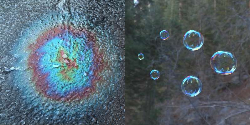
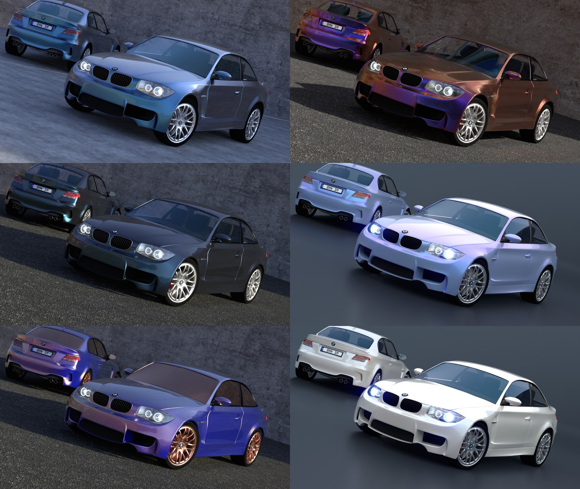
Example images (oil stain, soap bubbles, multichromic car paints)
Materials provided:

blend file: https://www.dropbox.com/s/k2lehy470xceuws/interference.blend?dl=0
1.1 How to use the script:
In a new Blender file, make sure you have set Cycles as the rendering engine. Then, on the Render tab of the properties window (where you also set render size), check the box that says ‘Open Shading Language’. You might need to turn off GPU computing to see the box. When you have created your object and added a material, make sure to ‘use nodes’, and then add (Shift+A) a script node. Select the ‘external’ option and open the .osl file provided below. Or, Create a new text block within Blender, paste the code there and select the ‘internal’ option. Then select the text block you just created.
1.2 Options of the script:
Inputs:
-
Top layer*:
[LIST] -
thickness of layer 1, d_top (in micrometer)
-
Index of refraction IOR_top of layer 1. RGB datatype: a value for red ®, a value for green (G) and a value for blue (B). Default (1.6,1.6,1.6).
-
Extinction coefficient k_top of layer 1, related to the absorbance. RGB datatype: a value for R, a value for G and a value for B. Default (0,0,0) = nonabsorbing
-
Middle layer*:
-
layer 2 thickness d_middle (in micrometer)
-
IOR_middle of layer 2. RGB datatype: a value for R, a value for G and a value for B. Default (1.6,1.6,1.6).
-
k_middle of layer 2, related to the absorbance. RGB datatype: a value for R, a value for G and a value for B. Default (0,0,0) = nonabsorbing
-
Substrate:
-
IOR / n of the substrate (base layer). RGB datatype: a value for R, a value for G and a value for B. Default (1.45,1.45,1.45).
-
k of the substrate. RGB datatype: a value for R, a value for G and a value for B. Default (0,0,0) = nonabsorbing
-
Wavelength*: the wavelengths to use for the interference effect, for the R, G and B channels.
-
IOR_outside*: the index of refraction of the ‘outside world’. Typically 1, but under water would be 1.33, for example.
[/LIST]
- Whether these inputs are visible depends on the conditional compilation flags, discussed below.
1.3 Outputs:
- F: reflected percentage of the light, per color (RGB), at the angle between the normal and the ray of light.
- F0: reflected percentage of the light, per color (RGB), at normal incidence.
- T: transmitted percentage of light, per color. Can be hooked up to a refractive shader.
- T0: transmitted percentage of light at normal incidence.
By hooking these up to glossy and refractive shaders, metallic and glass-like materials can be made. Examples are present in the blend file. Negative values which don’t make sense are not prohibited, and may lead to funky results.
1.4 Conditional compilation:
The OSL script has statements that are used for conditional compilation to maximize speed. For example, say you only want to use it to calculate the interference due to a single layer on top of a base material. Then, there is no need for the code to calculate the second layer. You can simply set this layer thickness to 0, and it indeed will be as if it is not there. However, the code for the second layer does execute. To circumvent this, conditional compilation is used.
At the top of the code you can use #define statements to in- or exclude parts of the code. The provided example blend file has actually three identical copies of the OSL code, except for the amount of layers that it calculates. This is controlled by the flags for conditional compilation. The current flags that you can #define are these:
SINGLELAYER
DOUBLELAYER
NONVACUUM
EXPOSE_WAVELENGTH
As you probably expect, SINGLELAYER includes just the code for a single layer on top of the base material. DOUBLELAYER includes code for two layers on top of the base material. If you don’t #define either, it will be just the base material (for example, for accurate metals). The NONVACUUM flag exposes the assumed index of refraction for the ambient medium. Typically that’s air, but maybe you have an underwater scene (n = 1.33) and you need to calculate what happens then. This allows you to change it. It has not been tested extensively by me!
EXPOSE_WAVELENGTH is a flag that allows the artist to set the wavelength for the R, G and B channels. At first, some values were hard-coded in the script, which of course can be easily changed by changing the code if you’re a programmer. However, I realize that often artists aren’t coders (or vice versa). Therefore, making the wavelength exposed in the shader node is an artist-friendly way to gain access to the internals. However, in many cases it’s just fine with the hard-coded values. Therefore, you can choose to expose the wavelengths to the outside, or to hide them altogether and maybe gain a little bit of speed.
2.1 Choosing values for n and k
The shader allows you to enter the values to use for the refractive index (n) and the extinction coefficient (k) for the red, green and blue channels. These values are often listed as a function of the wavelength of the light, for example at refractiveindex.info. Wavelengths that are perceived as red run from something like 625 nm to 670 nm, green is about 520 nm to 550 nm and blue is about 440 nm to 470 nm. Which wavelength you choose to use for red, green and blue depends on your own preference; there is no wrong choice, and the shader will behave physically correct regardless. Of course for different choices of n and k at slightly different wavelengths, the material is likely to change appearance slightly.
2.2 Optimized values of n and k for metals
So-called spectral renderers use the tabulated n and k values for each wavelength in the visible light spectrum to calculate what a material should look like. Cycles on the other hand only uses three color channels, one for red, one for green and one for blue. You might wonder what n and k values would best approximate the results of a spectral renderer. I have optimized the values of n and k for the metals that are included in the blend file to look as close as possible to the output from a spectral renderer, when the metal is illuminated with white light. These calibration curves can be found in this zip file: https://www.dropbox.com/s/uul8wbgso911svt/calibration_curves.zip?dl=0
Link to the script: http://www.pasteall.org/73796

