I’m applying a displacement map on a “table” I modeled for a scene but the map acts in a weird way… it seems that the displacement is “displaced” toward a point in the centre of the round object.
I need to say that this displacement is created from a UV map. Basically I created a round table using a cylinder and then I added a small depression in order to simulate the leak between the two parts of the table. The internal part should be made of wood and the external as a metal ring.
Now I applied the displacement but as you can see is seems pointing to the centre of the table.
Why this?
Should I create two different meshes? One for the wooden and one for the metallic part?
Should I add polygons [subdividing the table more times]?
Should I re model the table [or at least the wooden part] creating parallel polygons? At the moment it’s created as a normal cylinder where all the edges face the centre. Maybe I should retouch it in order to make sure to have parallel polygons whose edges follow the displacement map?
Hard to say for sure if any of these will wholly remedy the problem, as it may depend a lot on your toplology, so seeing a wireframe would help.
If you have a large “fan” of triangles making up the top of the table, that may be contributing, UV maps prefer quads. Adding concentric edge loops by subdividing will help but will still leave a smaller fan at the center – this you may want to remodel into quads. Then Unwrap again, most likely using Project from View while in Top Ortho view. (Numpad 7). This should give you the most reliable UV mapping of that surface.
Remodeling to have the mesh mimic the wood planks structure may be more than is necessary but will certainly give you a good unwrap and texture placement if done carefully. In that case making the metal rim & the wooden portion separate might help matters.
Hi chipmasque,
You definitely hit the target. The table is made of concentric edges… so I defnitely know what to do now… I need to remodel it in a way that the polygons remain parallel… I just hope I won’t have problems once I’ll have to create a round shape…
Hi… I’ve tried to setup everything in a different way but I’m noticing that id doesn’t work as expected.
First I’ve tried to create the circular shape of the table using parallel polygons instead of the concentric shape… but in this way the possible subdivisions are quite limited.
Secondly as you can see the texture seems “stretching” on the edges.
I’m posting the file… may I ask someone to help me?
Your help is so much appreciated guys… forgive me if I disturb for such small stuff…
Every time a person asks a question, before conducting research and gathering information, the hands on the doomsday clock move one second closer to midnight.
You are bringing about Armageddon , do some research on blender UV mapping, before you kill us all.
Did a lot of researches but all you can find is how to apply the displacement on a square plane nothing more. If you have something more detailed I’d be more than happy to consult it. There is the possibility I misunderstood something though as English isn’t my native language.
What I created is a round table made of wooden boards. The shape of the table is round and the wooden boards are parallel.
Usually in order to create round objects I use a cylinder but the round part is made of concentric circles and as seen in that way it doesn’t work. So I tried to re model it using parallel polygons order to follow the texture but also in this way I encountered problems.
The first problem is that I unwrap the cylinder using projection from view [top]. In this way I have my circle perfect, but the sides just repeat the last pixel of the image among the Z axis. So my first problem is “how am I supposed to unwrap it”? I want to use the Displacement as I would like to “move” the wood and “see” the spaces between a board and the other. But if I have the texture of the wood boards the problem applies to the side of the cylinder. I cannot see any space betweeen the axes here as I have no idea how to unwrap it in order to be able to make this happen.
The second problem is about the number of polygons. Displacement requires a lot of polygons to work and some of these can be achieved using a Subdivision Surface modifier, but in this very case the SS doesn’t work as not enough polygons are created and the wood seems “unrealistic”. If I model the table using a cylinder with concentric circles the displacement points to the centre, but if I model it using parallel polygons I cannot subdivide them too much as I get triangles in the process.
As you can see from the model I also tried to give a little bit of “roundness” on the edges creating cuts really close to the edges. For the vertical part there are no problems, but for the top there are… as I said the polygons are parallel and all I could do was extruding the edges in order to terminate the cylinder in the usual way [the most external part is a ring].
I hope this explains better what is my problem.
My question is… Did someone had the same problem in the past? I’d need to be able to “see” the space between the wooden boards but also at the end of the model [where it finishes on a round shape]. I need to be able to create a round shape but usually in order to achieve this you need to use a Sub surface modifier. If I use parallel polygons this doesn’t happen as most of the polygons on the edge of the circle become triangles.
If someone has a good advice is much appreciated!
Thanks to whoever would like to help
I also found a nice tutorial that explains how to use the displacement channel.
As usual here they use a plain and not a 3D mesh.
Ah, I forgot an important detail… I’m trying to create a close up image, this is the reason why the image should be “perfect”. As you can see on the edges it seems that the texture is “stretched”. I don’t know how to sort this out as in order to avoid the bad effect of a displacement that points to the centre I had to model it using parallel polygons. But in this way i need to subdivide a lot the centre and subdividing, the edges that are already small become even smaller. This is unclear I know but I hope it helps to understand!
Respect to what I have done in the file I would subdivide further the geometry of the wooden part of the table, so to get a good resolution, because the subsurf modifier has a limit of 6.
This is perfect! It starts as a “square” but it ends as a circle. I didn’t think to add additional rings outside the squared shape… I actually was thinking in a very limited way [concentric or parallel]. I was also posting an example [included].
In my project the sides won’t be shown as they’ll be covered by a metal ring [maybe I can add some rust just to marge it with the raw wood], but I used this as an excuse to lear the next step that’s how to displace it properly also on the sides. The top is perfect… I’ll also subdivide it more times in order to have all the polygons needed.
Regarding the “height” i think that I can do like this
I create a different map that takes half of the polygons of the side of the cylinder and I unwrap it from view [front] and an other that takes the rest and I unwrap as well from the view [back]. In this way I can also work on the deformation of the polygons on a curved surface.
Maybe I can just select the last polygon on the left and right to add a different texture [that shows the long side of a wooden board].
I place them on a texture that shows the sides of some aligned wooden boards [I come from Bolzano… tables like this are quite common there].
I add diffuse and displacement from here.
Just to make sure not to subdivide too much the "curve"between top and side can be as you did just a single line of polygons rotated 45° in respect top or side.
Thank you so much for your help! This works really great and I’ll definitely use this shape you suggested to model all the round shapes that require a displacement that doesn’t point to the centre!
Madquake: the main issue is how you have tried to unwrap the UV’s, you need to place seams to break the uv’s into islands to allow unwrapping to work correctly, no seams = distortion.
UV unwrapping works the same as unfolding an object in real life, take that lid shape you have, unless you make cut lines and separate some faces, flattening it will create distortion, this is what is happening with your table, no seams, no “islands” just a squashed one piece mess.
Your model can be absolutely terrible and still look fine if unwrapped correctly. (I’m not promoting bad modelling, just making a point about uv’ing)
#“Smart UV Project” will automatically break your uv’s into islands but will not always save you, it is better that you understand the how and why so you gain knowledge rather than just information.
That is why I’m being advising you to research rather than asking.
Research UV mapping in blender, or UV unwrapping in blender,
hint copy and paste “blender tutorial uv unwrapping”
ooh, just realized you are talking about displacement mapping not normal mapping, all the above still applies as you are also using a normal map image and mapping it in your node setting, and relying on UV mapping for placement of the displacement map.
Now the second part:
Displacement mapping
If you want to use the displacement modifier correctly a basic understanding of how the displacement works is required.
Above I was talking about normal mapping, which is per pixel shading.
Displacement works on physically moving vertices, per vertex, so for a clean displacement map, nicely spaced out vertices with poly count high enough to pick up detail is the goal. ( I mainly focus on game assets so don’t use displacement much)
The simplest option I think would be to use the “remesh modifier” to get an all quad mesh with perfectly spaced vertices, 2 options go really high poly and keep mesh as one piece and use seams or uv groups to assign different texture or materials, or break the mesh into 2 peices and only remesh the wood mesh, and have the metal ring overlapping, this would be ok as in reality the metal ring would overlap and sit onto of the wood. depending on personal preference you could use remesh followed by a subd and then displacement last, or just remesh at higher level.
Hi Zenitor…
I actually use seams… I’ve been working on some packagings and I’ve got the “unfolded” of the print. I definitely had to learn how to do it.
My problem here wasn’t “how to unfold” but “how to make sure that unfolding I don’t create a sharp edge”.
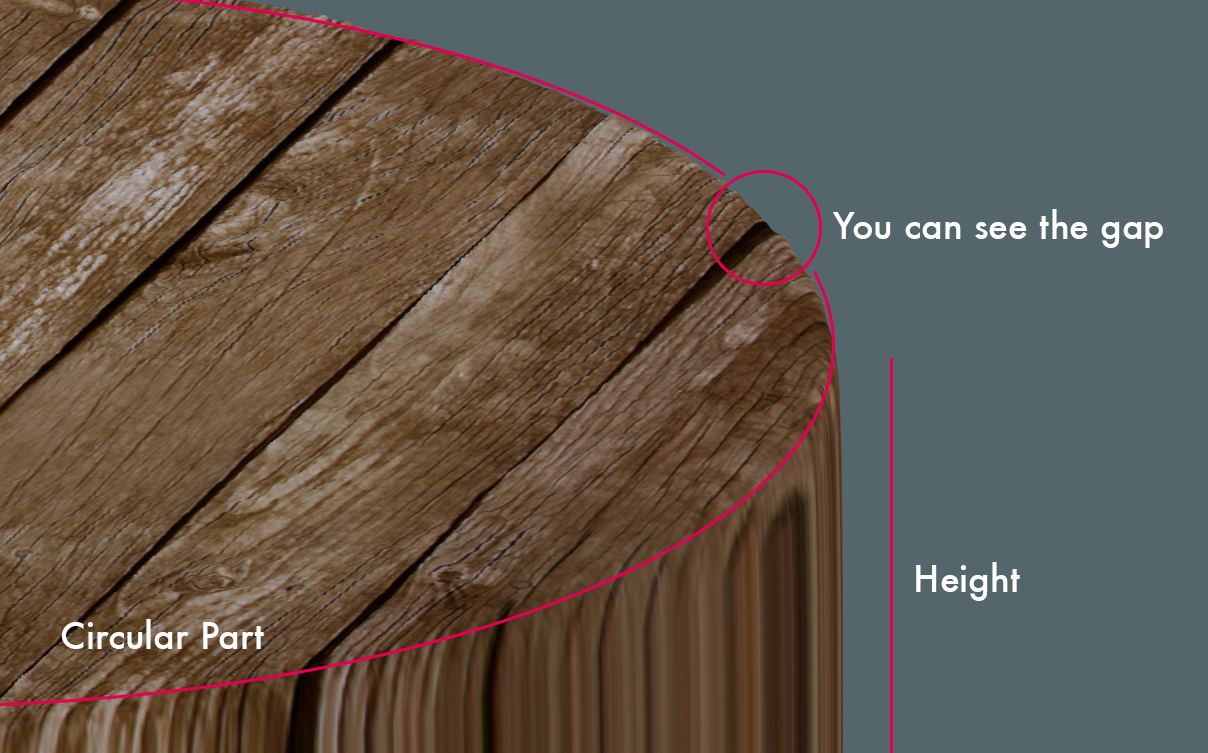
I explain better. My problem is more related with the usage of the displacement. I created a round “cap” for the cylinder. I mark the seams of the circle at the top and then I unwrap it properly. In this way what I’ll achieve is 2 circles and a rectangular shape on the UV editor [very roughly explained]. Now… I need to apply a displacement map on the top in order to create the gap between each wooden board. I still have the “height” [what in the UV editor is a rectangle] of the cylinder. Of course here I cannot apply the displacement as the wooden boards in the texture are seen from the top and what I’d like to get is having the nice gaps not only on the circular top and bottom of my cylinder but also on the height [if it’s not clear I can make a scheme]. When I’ll apply the displacement the height of my cylinder will be “sharp”. Basically if from the top there is a gap from the side there won’t be. How can I avoid to see the perfect circular shape of the height of my cylinder over the displaced top?
As you can understand my question is not related to how to unwrap or mark the seems but on how to make sure that the side of my cylinder deforms following the deformation of the top.
If this isn’t already clear I can post some kind of examples.
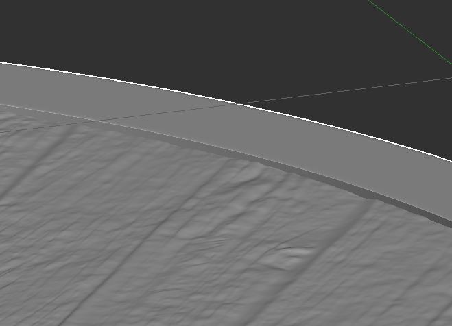
I noticed that Paolo has created a junction between the top and the side. He basically created a circle of polygons that are at 45° [basically the top is a plane at 0° and the sides polygons of the cylinder are at 90° - hope this is clear too]. In this way, despite the texture is a little bit deformed on these 45° polygons still shows the gap the interests me so much.
I think that this should sort out the problem that basically was:
How to avoid the displacement to be sucked to the centre of the circle [1° image I posted]. In that case concentric rings suck the image to the centre of the circle, while this new hybrid “square in the centre, circle on the edge” shape works perfectly [and can be subdivided too!]
How to be able to distort not just the top but also the side of the cylinder [again vertical side… what in the UV editor is unwrapped as a rectangle]. If you see my example the deformation works perfectly but the side of the cylinder is still visible as if it’s surrounding the top. I also understand why you spoke so much about UV unwrap… but I didn’t unwrap from the top as I’m not able to do it properly… I did it because I was trying to avoid to have the “height” of my cylinder un displaced and visible over the displaced top.
I actually already read the tutorial you posted, even if I prefer video tutorials [they work better for myself]. Thanks anyway for the link but unfortunately that wasn’t my problem
Although… now that I did a trial with this I can probably use the same texture to displace also the side [height] of the cylinder. I just need to make sure that the gaps fit.
Thank you anyway guys… for what I needed I could just have used a plain… but I’d have never learnt how to sort out the problem!!! Forgive me if I’ve been to picky but seen that I had this question in my ,mind I just wanted to make sure to have understood everything perfectly!
Paolo, if you want to visit Bolzano I suggest you to go after summer… in summer is quite too warm… even if you are from Florence the other city in Italy together with Milan being the warmest in summer.
I live in Manchester so in this very period of my life I’m quite far from home… Bt I suggest you to visit also the places around such as Renon, il Colle, Castelfeder, etc. If you need advices feel free to write me!
Sourvinos had the solution in his .blend, apply the displacement modifier using a vertex group to restrict to the table top only
(only thing to watch is the displacement will extend halfway past vertices so you might have to put in an extra edge loop to clamp it)
Then for the subd use mean crease or extra edge loops to restrict subd from deforming ring
you can also stack subd modifiers to get higher level of detail, this is also good for quick jumping into edit mode, first subd set to 2 and second 4 etc, so 1 click on top subd will reduce quickly.
You can’t assume that one single unwrapping method will work OK for all possible surfaces. For example, you can select the upper round surface of the table and use Unwrap>Project from View(Bounds) while viewing the mesh in ortho mode Top. This will apply your texture as if it was projected square-on to the table’s top, which is what you want. You can do this for the wood portion separately from the metal portion. Use Seams to divide these separate areas from one another before unwrapping.
Then select the rim of the table and use Cylindrical>View from Equator to unwrap that portion of the model. Be sure to use Seams to divide the rim into portions so the texture does not get stretched; you can stitch the portions back into a continuous strip in the UV Editor window.
Rinse & repeat for any other portions of the model not unwrapped, choosing the best Unwrap method based on the model’s form & topology. This method requires careful planning & a little extra work but the results will always be better than trying to get a single Unwrap method to work for all possible surfaces and all possible texture applications.
Sincerely I don’t know how to get a correct displacement on the sides of the table by using just the same texture; by projecting the height polygons from the side view you can get the cuts between the boards to match, though the wood grain will be wrong for both the front and the lateral sides, as you can see.
One possible solution could be through a procedural wood mapped in object coordinates, and multiplied with some stripes to get the gaps between the boards; sadly I don’t make use of Cycles, so I cannot help here.
Currently I have no chance to travel as I wish, from now on it could be the right time to get there I think, winter is to be avoided as well (I don’t like cold weather so much, and in Florence we have more than enough anyway).
I didn’t realize this is what the OP wanted to do, but of course that will not work well, no way you can extrapolate a proper end grain by projecting from a typical wood surface texture. You’d need a procedural that is designed to be a true solid so the surface of cross-sectional cuts (end grain) is automatically produced. This is particularly true since in the round table the end cuts of the planks are not perpendicular to the other plank sides, they are curved at various angles to the grain direction. Perfection is always very complicated lol.
At best you might be able to place the individual rim faces such that the result at least vaguely resembles the proper grain, but to achieve a perfect displacement as the surface crosses from table top to rim? Highly doubtful.
I’m doing some experiements.
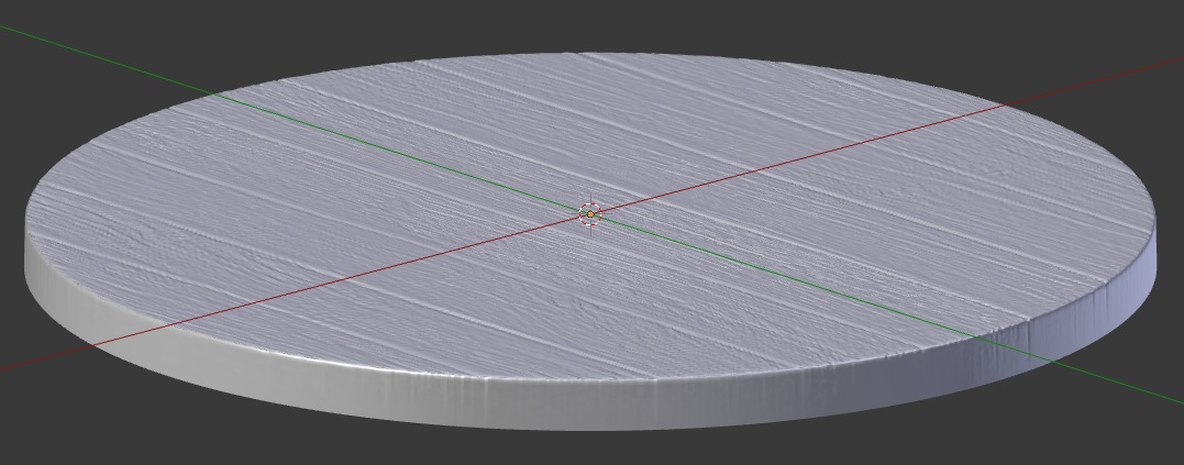
I need first to thank you all as now I feel more confident using this method and the results are a lot better. I re modeled the table top as at the very first time [center and ring all together] and I created a UV map. I already applied the displacement map and I have to say that now, without texture applied it works good!
What I was doing wrong was not having polygons at 45 ° with respect to the other planes. I usually create the smooth edge making a cut close to the angle on both the sides [0° and 90°], but in this case this wouldn’t have worked as the edge remains straight [90° angle] and the side of the cylinder once displaced goes over the top plane.
Your examples have been great as at least for this very project now I can see enough “gap” that simulates the real space between two wooden boards.
I don’t know how I could create a real disc [side as well] like the one of a wooden barrel [just the top not the entire barrel]. The last example of sourvinos seems working well [he doesn’t have the metal ring around like I do so you need to see the thickness of the boards].
As chipmasque pointed out this is hard to achieve as the image is a lot displaced on the side as on the UV editor the polygons are quite small and this means that a small portion of the image will be stretched a lot.
My personal idea was to take a picture of a normal table’s side [square table] made of wood. Unwrapping half a side of the round table on this texture making sure that the number of boards is the same as the once on the top. Stretching and deforming the projected polygons you should be able to achieve a decent result [even if I noticed that every time I do this with a packaging some parte never fit properly.]
If you are curious to understand how this could be achieved I’d be happy to keep this conversation on!
By the way thank you so much for your advices so far… I’m really happy that I learnt this… and it’s all thank to you!
The part of the rim that you can’t convincingly reproduce with just the same texture is where the wood is cut across its fibers, there it looks like ‘points’ rather than ‘lines’, and along around it turns into lines again.
That’s why I suggested a procedural texture in object projection, it would be spatially coherent.
The other way around, that is, by taking a picture of a wood board from the side crossing the fibers, and than projecting the mesh sideward ‘from view’ in blender, the stretching could look more natural, maybe (just on the side o.c., not on the top).