First of all I want to say I’m new to this forum, but certainly not to Blender
I started using Blender more seriously/heavily in 2015 and now into 2016. Before Blender I used 3ds Max since 2006 when I first discovered 3D modeling with great interest.
My main goal with this forum is to get help with my Work In Progress here, constructive criticism and of course nice feedback on my work
I started on my current model of this ship on August 6, 2016 and have come quite a long way, especially on the hull! But my main problem to tackle right at the moment is that
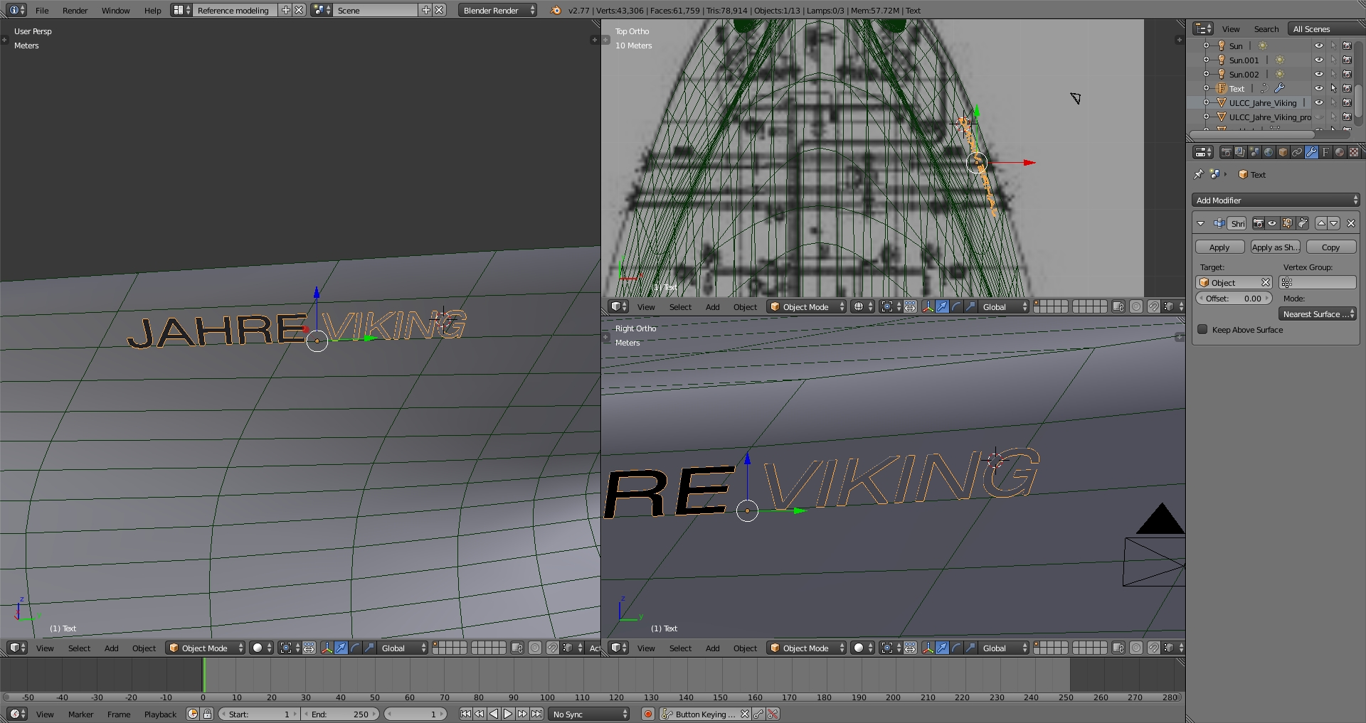
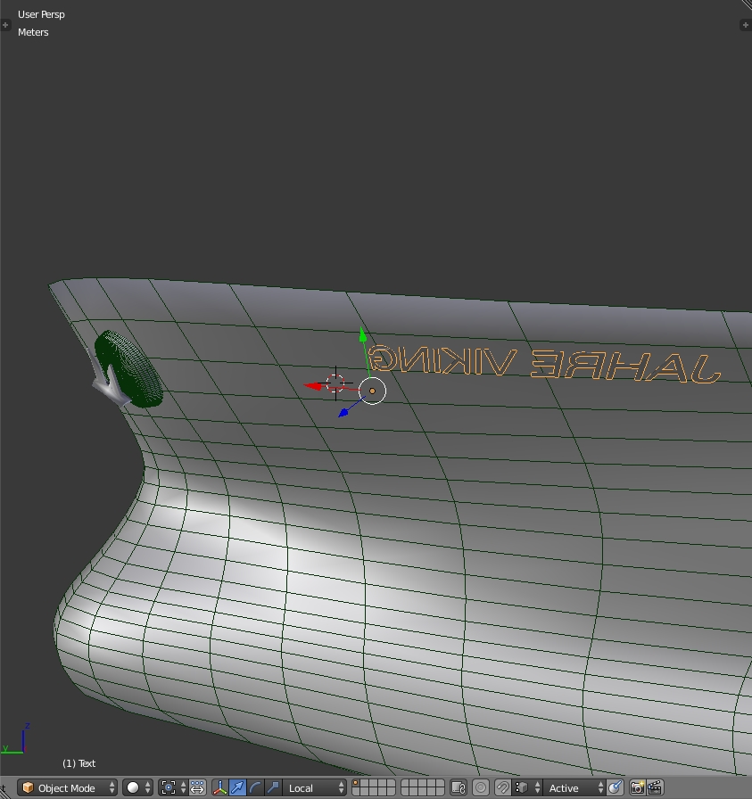
I want to mirror the name in the bow from the starboard side to the port side.
With the shrinkwrap modifier in use, and the text in a specific rotation, it’s been a headache to achieve what I want. So, my first question to this open community is:
Could somebody help me mirror the text (which uses the shrinkwrap modifier in order to stick to the hull, like it was painted on) to get mirrored correctly on the other (port) side?
that is a very interesting project u taking on, and I d like to see you progress. I d like to take on a vessel in the future but for know, don’t have the skills
firstly, could you let us (me) know, how you have solved the “jahre viking” problem?
As for your other issue with the “holes” in the hull (I have no clue what they are properly named), I had the similar problem using boolean to make my supercharger opening. The hole wouldn’t be clean. After investigation, I realised that faces surrounding the opening were too large and were overlaping the opening. After I added extra edges in crucial areas I solved myself the problem.
I don’t know if this will help you. I am new to blender and might be wrong. But it sure helped me wiht the similar issue
When I first was going to reply, my stupid browser deleted everything I had written… thanks a lot… not…
Anyways, thanks for your reply Lukasz I basically solved the naming problem (if that’s what you meant) by creating a text object, using the shrinkwrap modifier on the hull, then I convert the text object to a curve, and mirror it along the hull, using the hull as the mirror object. Then, I mirror the mirrored name along it’s local X axis (I believe it was it’s local X axis, as I had to rotate the text object 90 degrees on the X axis, and then 90 degrees on the Z axis, to align it to the hull as much as possible).
Oh, and thanks once again Lukasz for your tip on the holes, I will try it out and keep you posted
I know exactly the feeling and what you mean When you got something that can put a halt to your WIP, it can drive you crazy! But I’m really happy that you figured it out, for us Also, here’s the latest update at YouTube of my WIP
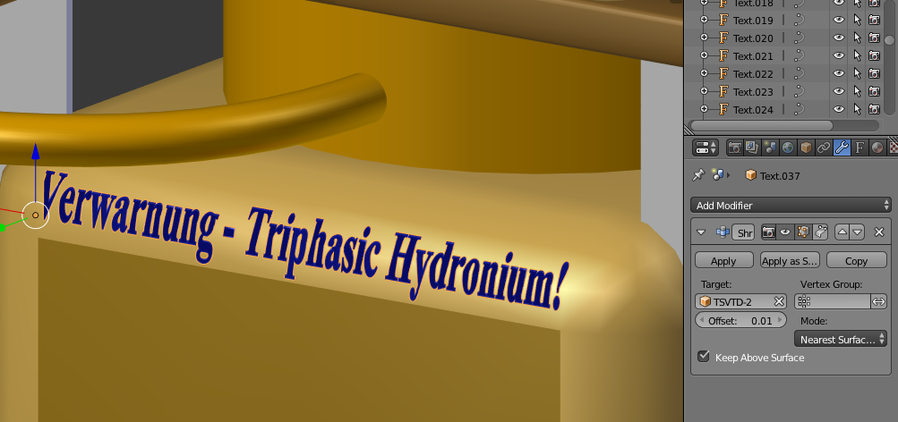
You can see I have checked the “Keep Above Surface” Checkbox and set the Offset to 0.01 - in my case. For yours, you may need to adjust the offset value so all the text is just showing. Then you will need to duplicate the text for the other side - if you set the justification to be Centre for both Horizontal and Vertical alignment it is easier to align since both text objects will have the same X and Z locations on your model. Then to make it look really nice, rotate the text so it is close to the orientation of the hull at the point it is near. Make sure the text sits just outside the hull mesh, rather than a long way off.
There is no need to Convert to Mesh as this will create lots of Tris (3 sided polys) rather than leave the text as a text object - hope this helps you!
Cheers, Clock.
EDIT:
I forgot to say that if you want the text to be extruded so it has 3 dimensions, Apply the Shrinkwrap modifier first (Click the Apply button), then set the “Extrude” value of the text in the Text panel. If you don’t apply the shrinkwrap it will squash the Extrude down to 0, so won’t look any different.
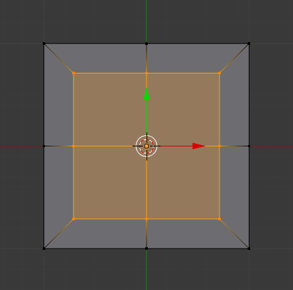
Select say four polygons as I have here and key i - drag the resultant edge loops inwards to make this:
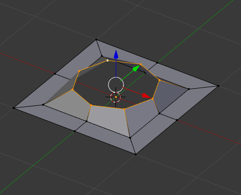
Delete the new inner polygons and add a circle of the same number of vertices as the hole - 8 in this case:
I have then selected the inner vertex ring and SHIFT selected the circle, then keyed W => “Bridge Edge Loops”. Then I just moved the circle up a bit to give the impression of the hole being flared, then added a Sub-Division modifier:
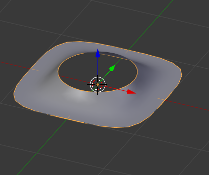
This method keeps the rest of the topology outside the hole intact and provides for a smooth hole. A circle of 8 vertices with a Sub-division modifier becomes a smooth circle. There is always a danger with using booleans of getting Tris or nasty shaped Quads; that doesn’t look good on your finished model.
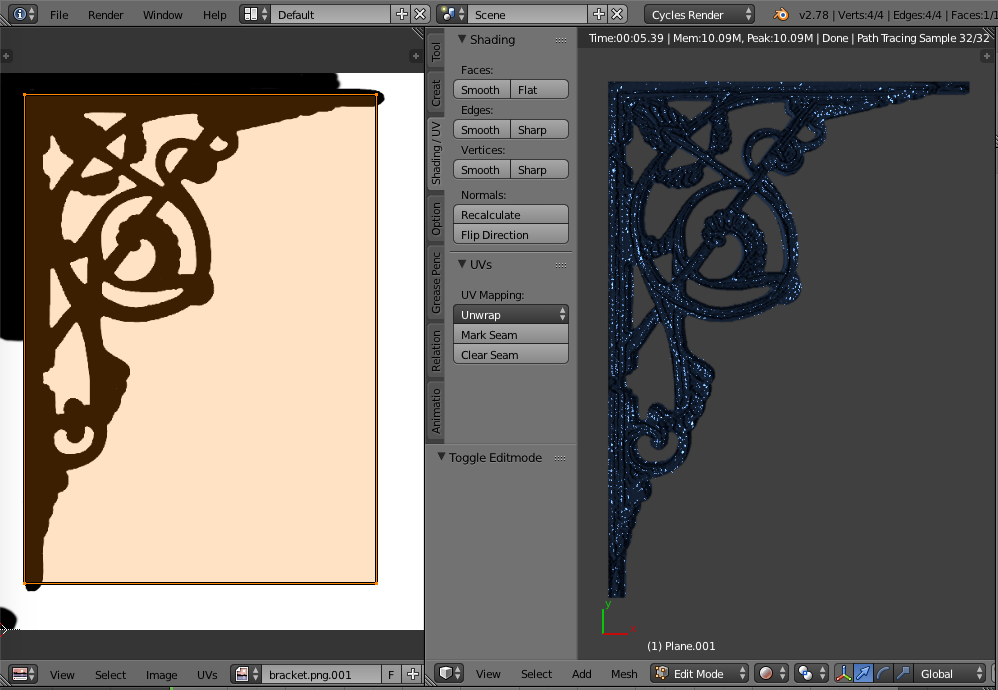
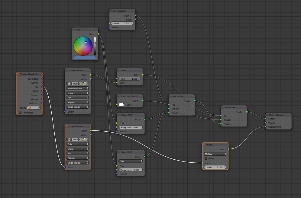
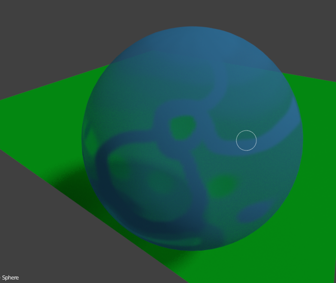
Straight forward holes, for windows etc. can be done using a Transparent Shader mixed to your main material using a Black and White Image to feed the Mix shader “Fac” - this means of course that you have to UV map the required area of mesh first, but it avoids all distortion in the mesh by having a hole this way. On the B/W images Black is a hole - White is solid. The Transparent shader must be in the top input node to the Mixer and it’s colour must be white. Any grey areas on the B/W image will be “ghosted” i.e. not fully holes or not fully solid, depending on the grey level.
Cheers, Clock. :eyebrowlift:
If you are cutting a hole in a curved surface you can shrinkwrap the circle (make it a new object) to your main mesh, Apply the shrinkwrap so its permanent, then join the circle to the main mesh - Select Circle, SHIFT+Select main mesh and key CTRL+J, then the circle has the correct profile for the main mesh.
The second image is the photograph of the bracket, I got the first one by whacking the contrast on the photo up to full in ImageViewer on my Mac - then saving as a new image.
Ah… I didn’t know that! But of course, this tanker (being the world’s biggest ship ever built) had many names… Seawise Giant in 1979, Happy Giant in 1989, Jahre Viking in 1991, Knock Nevis in 2004 and finally before she was sadly scrapped; Mont in 2009…
Although she had her up’s and downs… she was bombed in the Iran-Iraq war in 1988… being rebuilt at the Keppel shipyard in Singapore in 1989 I think… But she’s not “really” scrapped mind you… she lives on, in my computer
Haven’t posted here about this problem before, but here goes…
When I export to DirectX to the simulator I’m creating my ship for, the coordinate system is messed up? I mean, the simulator somehow seems to think that the Z axis is up? Maybe I’m wrong or so, but it seems to think my ship is completely paper-thin along from bow to stern?
I export to DirectX with Y axis up, the ship imports just fine, I can see it and all. BUT the game/simulator (Vehicle Simulator) seems to think that the ship is, as said before, paper-thin from bow to stern?
Well this is probably down to 3D convention when it comes to the Axis system. Most systems including Blender obey the convention that positive X is left to right, positive Y is front to back and positive Z is down to up. So you would see X & Z axes in the Front view, and X & Y in the Top view. Try rotating your model so it complies with this, Apply the rotations (Select All Meshes, key CTRL+A => “Rotation and Scale” - that will also fix any unapplied scales) The Transform boxes should show 0 for all rotations, and 1 for all scales in Object Mode, unposed.
If you press Numpad 7 you will see the Top view, Numpad 1 will show Front view.
Cheers, Clock
EDIT:
I have just noticed that your X scale for the hull in your first post is -1 not good! You need to apply the scales…