Not all objects have the scale of 1,1,1 (door) so should select and apply scale (ctrl+A -> scale).
Objects “front panel” and “usb” are non-manifold, meaning the meshes have errors. Front panel object has holes, and usb is just a mess with holes, interior faces, and also overlapping geometry which isn’t a mesh error but can become a problem. I get that you don’t care since most of that isn’t seen, but it’s not valid geometry.
The way you can check mesh errors is by selecting non-manifold in edit mode. Select none, then either from select menu -> select by trait -> non-manifold, or ctrl+alt+shift+M and if something gets selected, those are areas that need attention. Might not need fixing if it’s an open edge for a reason (edges connected to just one face).
Otherwise not too bad as far as mesh validity goes. Didn’t spot concave polygons which can be a problem and non-manifold check doesn’t recognize. What can be a problem is to use as little edges as possible and using n-gons (faces with more than 4 sides) instead.
The mesh is not better when it has as little edges as possible, nor is it better when it has as little polygons as possible, nor when rounded surfaces are defined with a lot of geometry. The mesh is good when the structure fulfils its requirements and optimal when most/all elements in it have a reason being where they are.
But why are n-gons a problem? For one editing a mesh with n-gons here and there means stabbing it with a knife tool until someone or something bleeds to death. Selections become harder, eventually can’t even read the structure anymore and it’s a mess. They’re not always a problem, relatively safe when they’re on a flat surface (planar) and convex.
Still not out the woods with n-gons. Those can distort when UV unwrapping. The mesh had seams and it was unwrapped, lots of distortion. Knowing that the unwrap method can be changed the resulting UV map made more sense. The back face which is an n-gon unwrapped nicely but there is one at the front that won’t co-operate
Even if you don’t have to care about a nice edge and face flow that much, it’s still better to make sense of the structure.
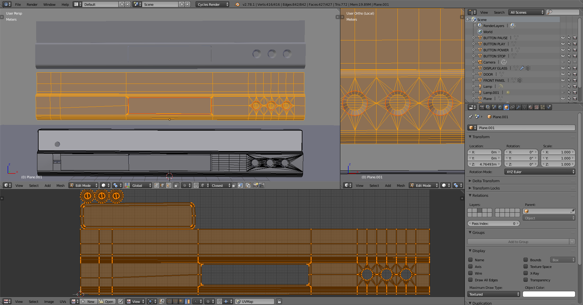
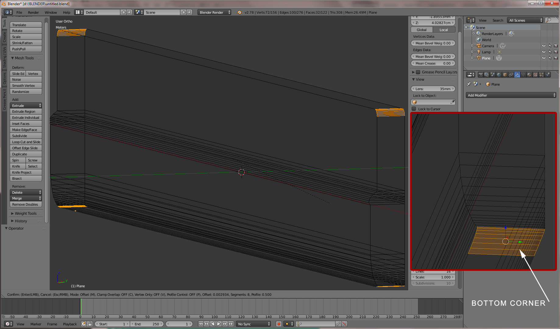
There are many flat areas so the faces on those could be whatever as long they’re convex but I started with a plane and cut quad sections to where each of the indentations/holes are. That allows to isolate each of them, making sure the surrounding geometry keeps convex polygons even with the rounded corners, and most importantly the curved surfaces consist of quads. I could also easily select any of the areas and for example remove one of the three indentations on the right.
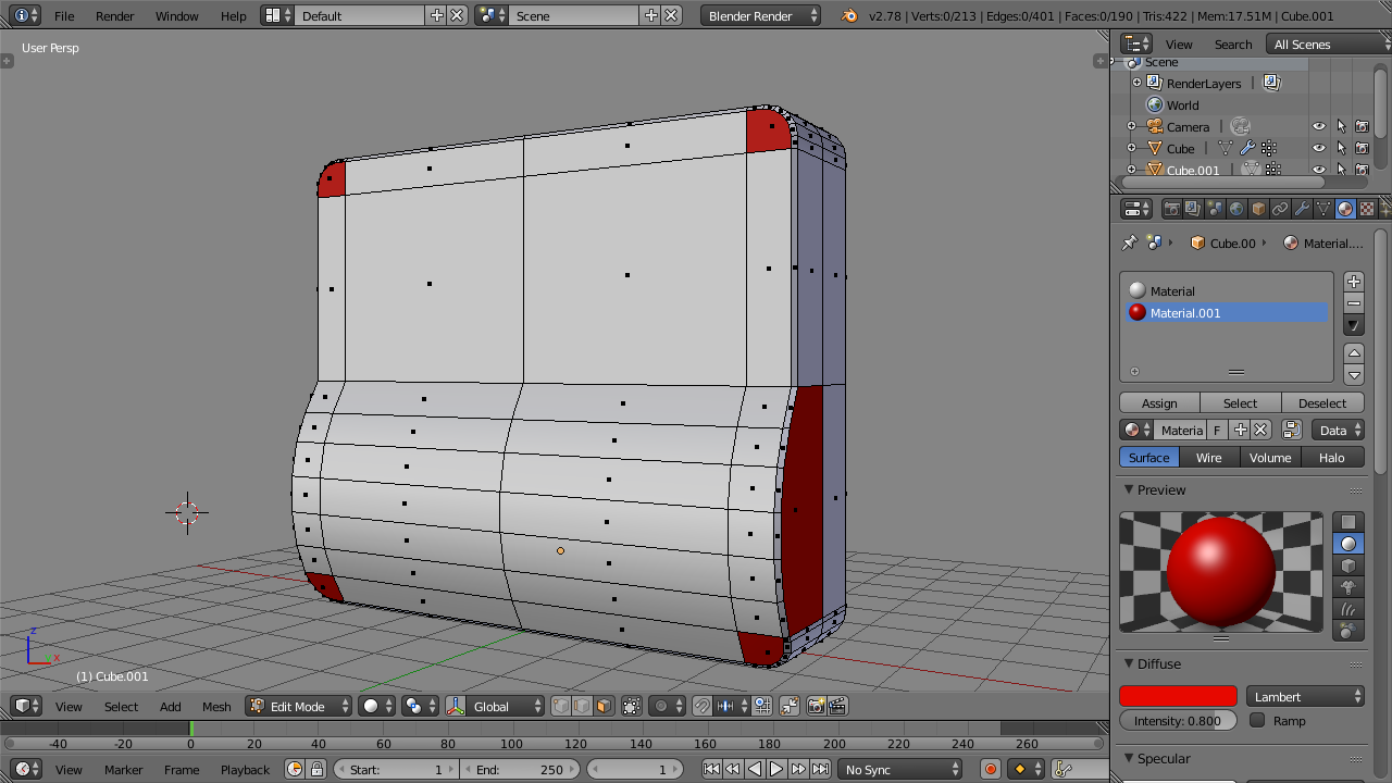
The mesh now has triangles, quads and an n-gon. Marking seams and unwrapping worked on the first try. The UV’s for the middle indentation is not perfect but workable, and it’s not skewed because of the n-gon but because I didn’t add seams and give it room to unwrap any better, easy to fix.
Sure the mesh could clearly have less polygons but I don’t know a reason to remove them. I do know 4 reasons for keeping this structure instead of reducing it to as little polygons as possible, including that in its current state I can easily reduce geometry if I get a reason for it.
 ) .
) .
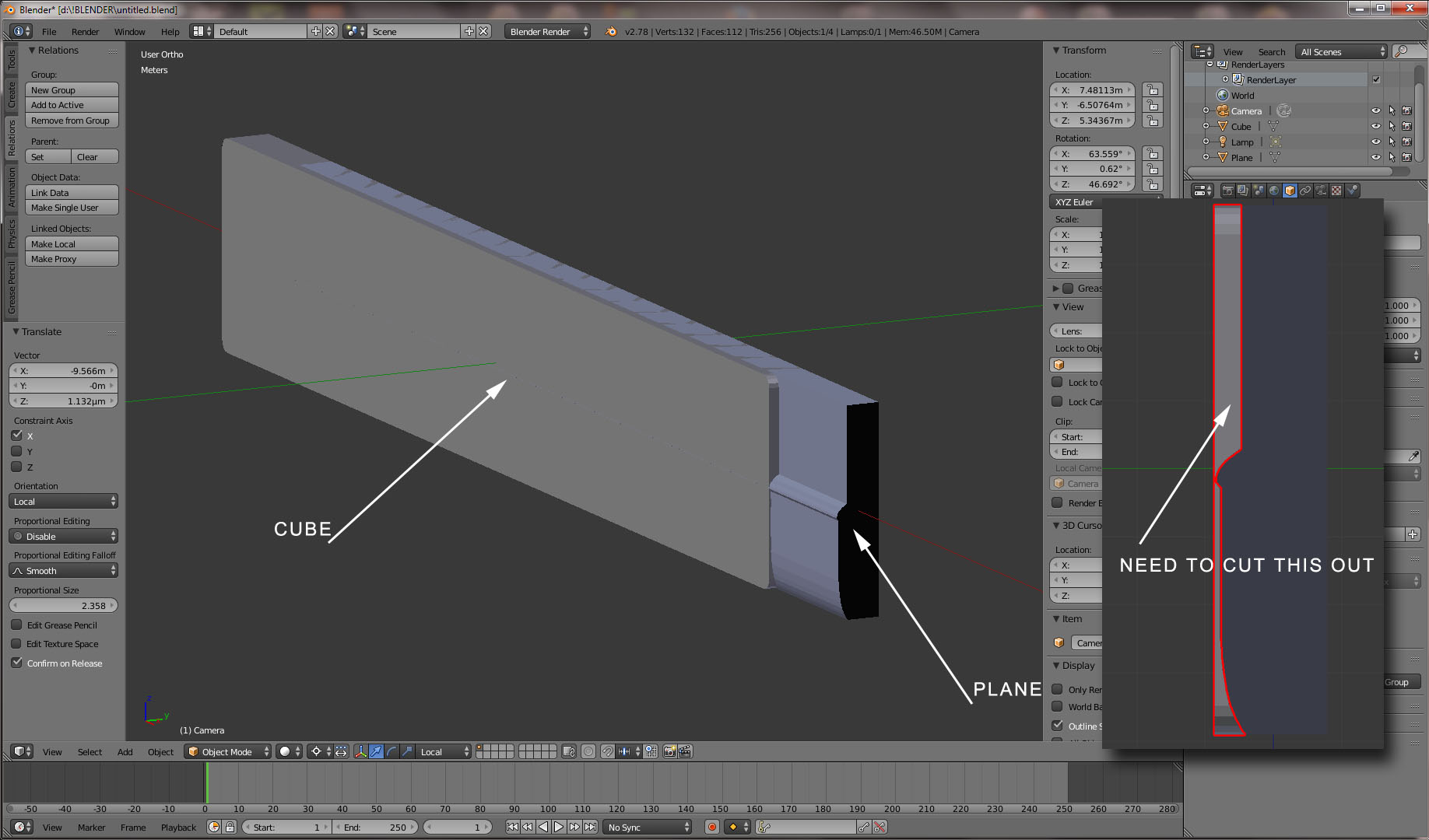
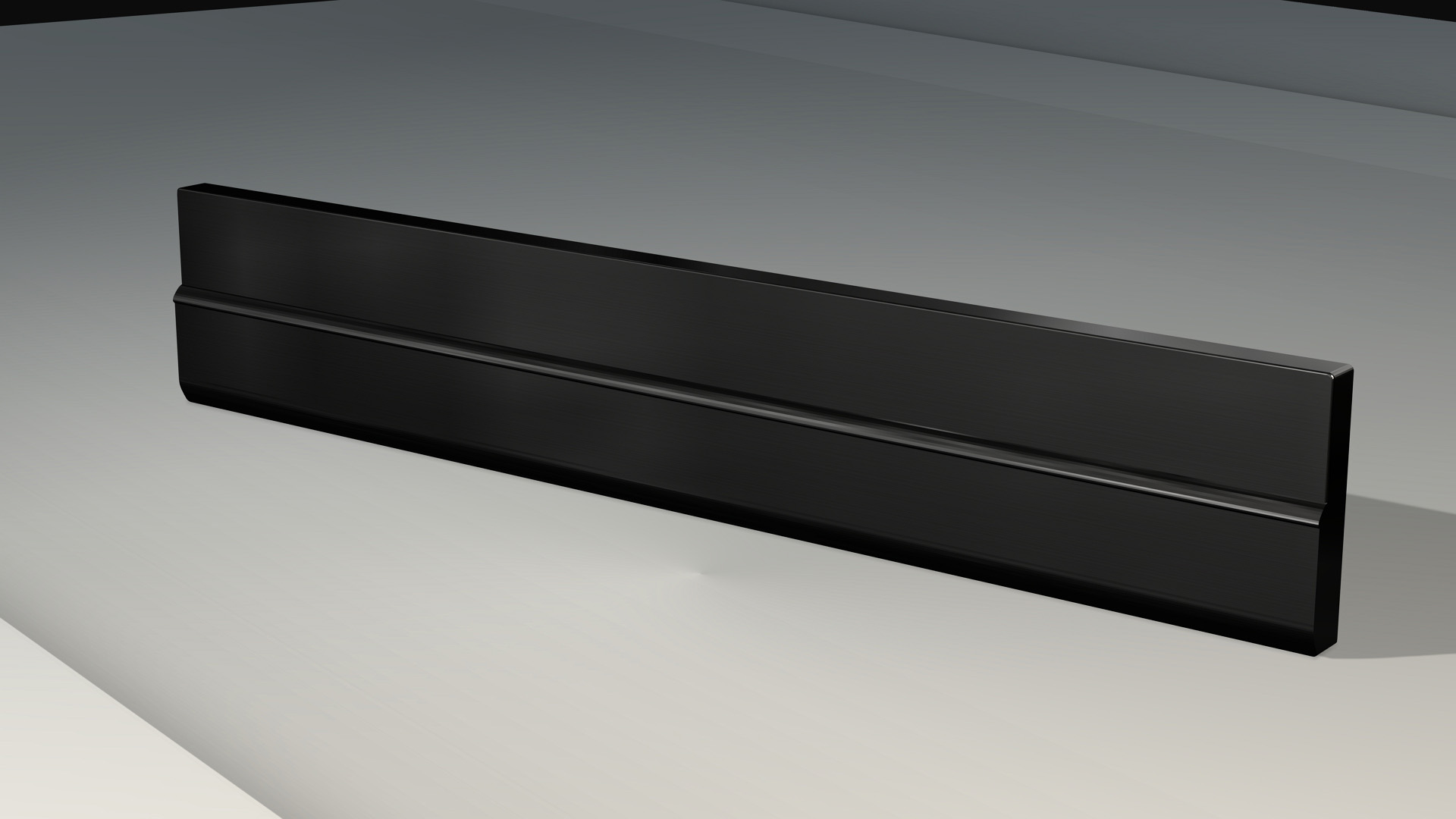
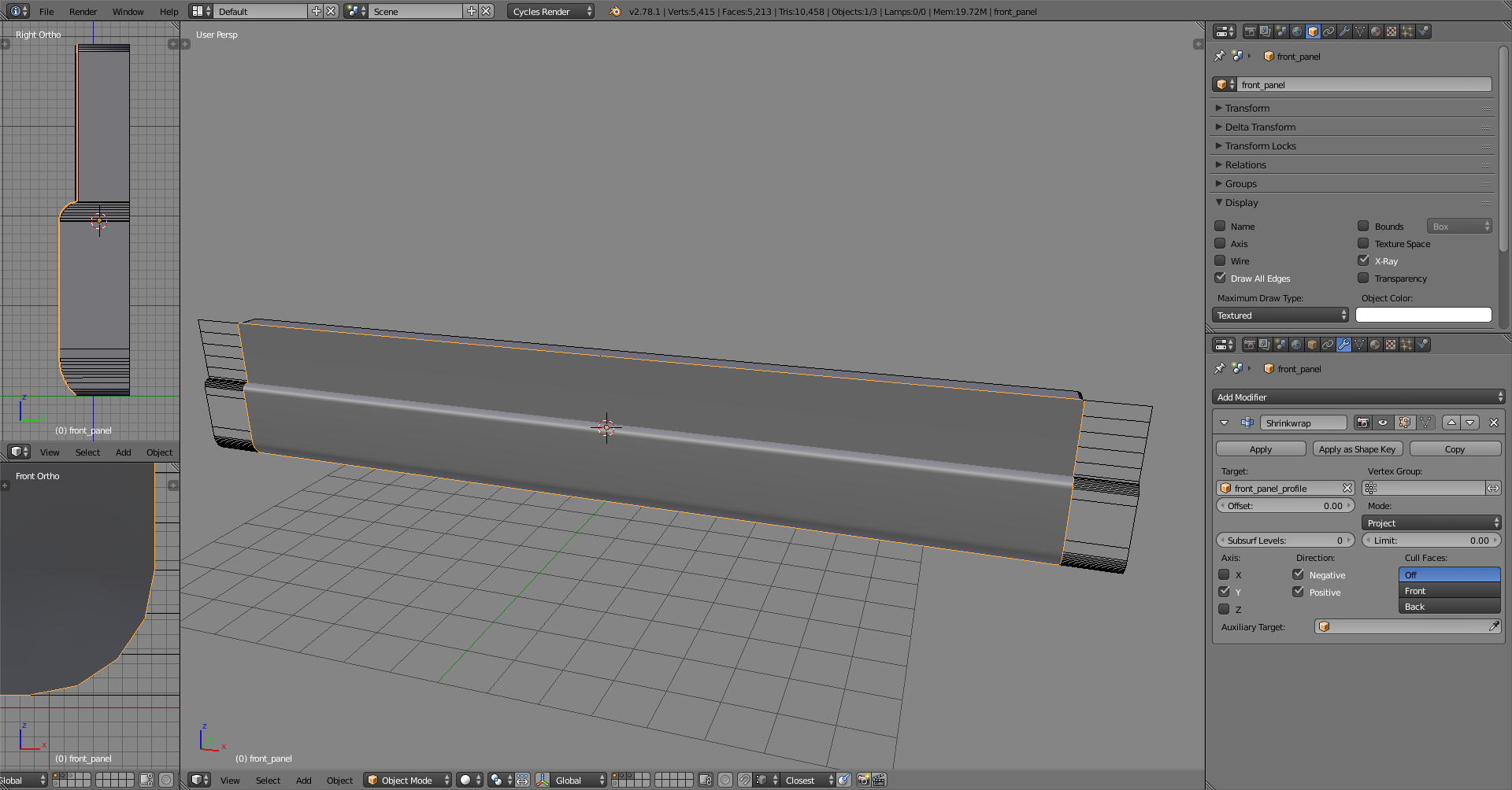
 (don’t know what I was thinking), but you may have been able to model both at the same time. Started with one cube and used the knife tool to cut profiles for both at the same time and filled polygons where needed, or using a boolean modifier to cut one shape from the other, or duplicate the faces from the one you have made flip the normals and extrude the edges out to form the rest of the shape, there are really many paths to take, but the path you take depends on the end result you wish to achieve and how fast you want to get there. A good idea is to study JA12’s vids as well as many others, from any application really, and apply/translate those skills over to Blender. There is a lot of good stuff out there for you to learn from.