found many others with the same problem but did NOT find the solution here or anywhere else so…
I rig my 130RS to spin the wheels with the movement of the car - using the transformation constraint to rotate the wheel about 140 degrees every 1m of a movement a it works fine … on straights!
When the car follows the curve and rotate around its Z axis the wheels stops spinning cause its NO longer moves around the GLOBAL Y axis but all the settings in the transformations are set to use the LOCAL ones! The car moves on the LOCAL Y axis all the time but despite its set it looks like Blender uses GLOBAL one for the transformations … why???
Does anyone know why this is happening?
I also tried to use AnimationNodes instead of constraints but with the same result…
Sincerely, JayM
PS: I could provide .blend file if needed but I think everyone experienced in car rigging knows what I mean.
Yep, been there done that! So the solution is to use bones since you can rotate them about one axis and still keyframe rotations about another and they persist.
It dates from end of 2014 I think, so it was done in an older version of Blender, I took a quick look at it and it still works. You may need to play with the drivers a little depending on the size of your wheels, etc. You might like to change them to scripted expressions, but bear in mind that rotations in scripted expression drivers are in Radians NOT Degrees and there are 2 + pi Radians in a full circle of 360 degrees. Essentially you need to convert the circumference of the wheel along the track to one rotation of the wheel. So if the wheel is 2 units diameter it turns once (2 * pi Radians) as the wheel moves 2 * pi units (6.26 approx.) along the track. A wheel of 4 units diameter moves 12.52 approx. units for one rotation, etc. :spin:
THX for the answer mate … sadly I do know NOTHING about how to control bones/drivers or even how to move the whole thing to see the wheels spinning but I will try to catch up with it - THX again.
But if U mean that I have to multiply the rotation according to path to keep the wheels spinning right than what about speed changes (accel/decel)???
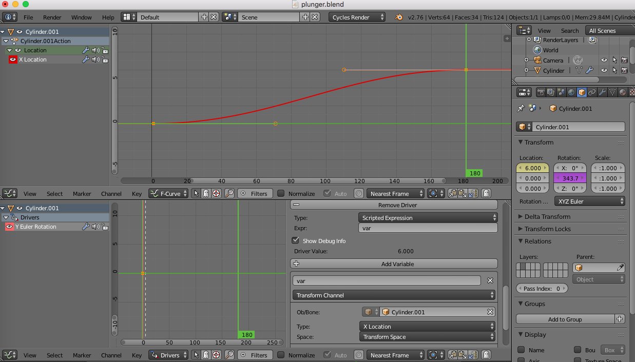
OK, so if you make a simple cylinder of 2 units diameter and keyframe its rest position, then keyframe it at say 6 units away, the default F-Curve will be of Bezier form, so it will give you acceleration and deceleration at the ends of the cylinders travel. The driver would then have the cylinder as the target object and if you move the cylinder in X, use X Location as the Type in Transform Channel. The driver would then be var (The variable), so the cylinder rotates 1 Radian per unit of movement. So if it moves 6.25 units it rotates 6.25 Radians or one full circle - equal to the circumference of the circle.
Take a look in the Graph Editor in F-Curve mode now and you will see the movement curve and note it is a smooth curve at start and end - this is what Bezier F-curves do. You do not have to worry about accelerations as Blender does this for you, if the rotation of the cylinder is based upon its location in space.
You can move the F-Curve “Handles” to increase or decrease the acceleration, i.e. move them closer to the keyframe point and the object accelerates faster.
To setup a Driver, use the Graph Editor in Driver mode. To insert the driver, RMB-Click the axis of rotation in the Object Panel => Transform section and select “Insert Single Driver”.
I thought that it could be done by parenting or something and I can only move the vehicle it-self and the wheels will follow … or not? One way or another I will look at it during the weekend and hopefully it will be a success ;).
JayM
PS: Despite Im 36y old the math is NOT a problem mate
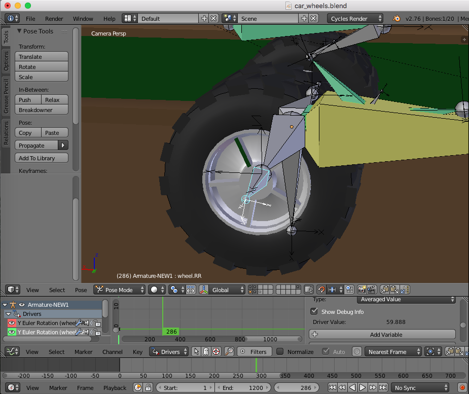
If you parent the wheels to the car, they will also inherit rotation from the car, so won’t rotate even if they have a driver in place. So bones cure the problem since a bone can be parented to another bone without inheriting rotation.
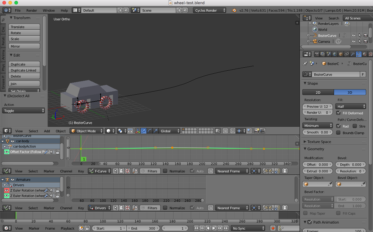
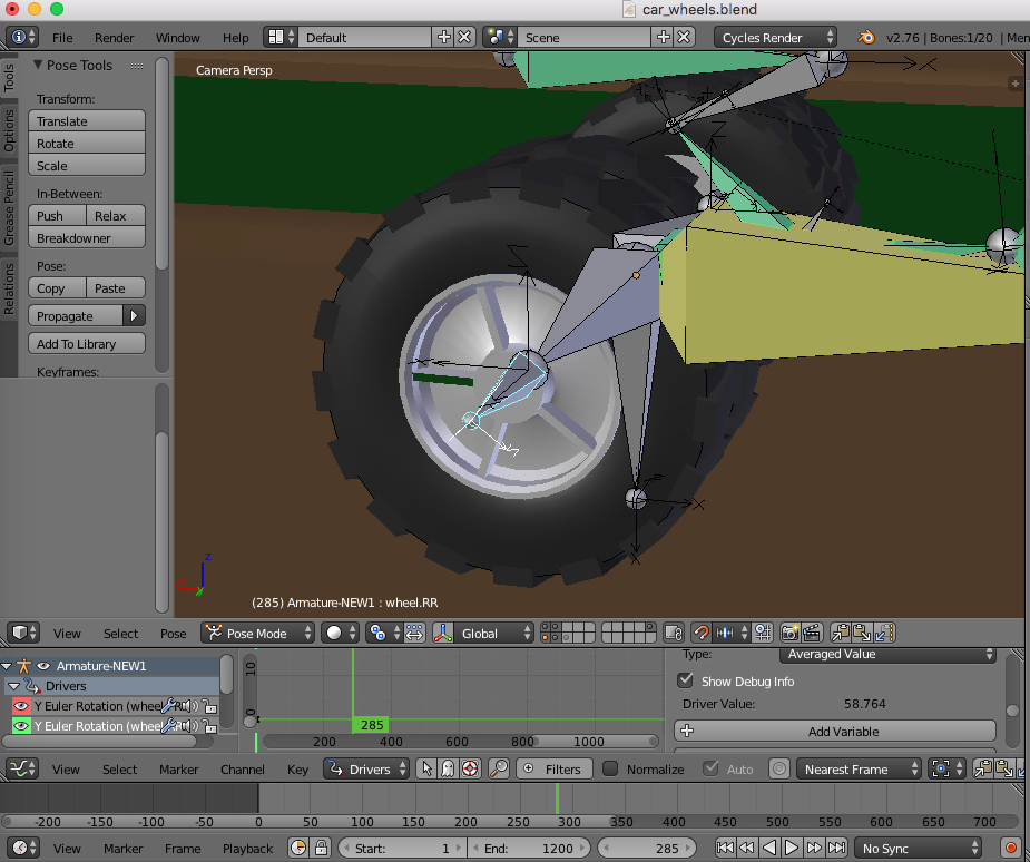
Note! The car accelerates slower than it brakes - this is because I moved the “handles” of the Bezier curve in the Graph Editor => F-Curve mode. The car has the follow path constraint and the armature is parented to the car. The wheel bones use the car as the target object rather than the root bone in their drivers, this avoids a cyclic dependancy where one object is dependent upon another that in turn would be dependant upon it, if I had used the root bone to drive the wheel rotations.
Cheers, Clock. :eek:
PS. I don’t know if you know this already, but you must check “Autorun Python Scripts” in User Prefs => File tab or the drivers won’t work if they use scripted expressions.
I checked Yo previous .blend file to see the anim of that “undercarriage” and slow it down to see the rotation of the wheels on that “S” curve and guess what … it does NOT work! During the 1st right-hand bend the wheels stops rotating and the problem is more or less the same as with the constraints I made on my car…
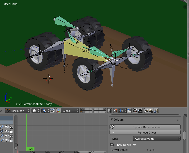
If U have Blender 2.77 try to check Yo file car_wheels.blend to see the problem PLZ. And yep, I have the run script option enabled.
Sincerely, JayM
PS: The problem is also in Yo second file wheel_test.blend. When I edit the curve to make the car turn 90deg to the right the wheels stops rotating!
when U check Yo file on frame 280 and later and go frame by frame (not play the anim, its fast) You could see that the wheels does NOT almost rotate… The inner part of the wheel (allu) visibly rotating on the first and last straight but NOT in the middle one despite the rotation should be constant on all that straights, right? (except the accel/break phases)
When I played the anim it looks OK but when I zoom in and go frame by frame the rotation is NOT right imo.
Sincerely, JayM
PS: Btw, if Blender did what it has to (uses LOCAL +Y for transformations) there will NO be such a problem so I think its a program problem because when I try to use LOCAL Y the constraint use GLOBAL Y instead (as it looks to me).
You can see the wheel IS rotating, just at approx. one spoke spacing per frame, when you render the animation, put some motion blur in place and it will look right. You often get this effect with motion - the camera takes a frame every 24th of a second and the wheels turn approx. 72 degrees (in this case) so it looks like they are stationary. If you watch a video of a real car, you will see sometimes the wheels appear to be going too slow, appear to be stationary, or appear to go backwards - its just how the video process works. You can get the same effect yourself by spinning an object under a neon light or strobe, it appears to be moving all wrong.
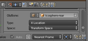
Just read the Driver value in these two images - second is larger than the first.
I rest my case M’Lud!
Cheers, Clock. :eyebrowlift:
EDIT:
The Drivers use X Location for the Icospheres in Transform Space…
Yep, U R right man! It looks stationary cause the angle was exactly the same like between those spokes… One way or another I dont really understand all that bones/spheres/drivers thing so could U write what bone do what?
I know its probably a lot of work so only if U have a time bro…
Give me a couple of days and I’ll try to explain what everything does. The most important thing to the whole setup is the two icospheres (on a hidden layer) that have the curve modifier to make them move along the track. I tried for weeks to get this to work properly and even had some help here two years ago. The problem is that you can’t add a curve modifier to an armature, you can’t use a Follow path because it is axis dependant, so you can’t turn more than a few degrees without it going pear-shaped, so I had to find another way to do it. Once I worked out that bit, the rest was a lot easier. Turning linear motion into angular motion in Blender is quite easy - just remember that every rotation in scripted expressions is in Radians and that if you move an object of 1 unit radius the amount of rotation in Radians is the same as the forward movement in linear units.
More when I have a little time to write it up. I might even put the write-up on my website clockmender.uk in the Blender tutorials page.
Did something a good while ago, the trick was to measure the total length of the path. (Used to be a script for that which would calculate a value up-front and let you manually copy it, not sure if the script is still available for the current version of Blender. Unfortunately something is still wonky with paths in Blender such that there’s no automatic distance attribute or property associated with them.) Then you figure out the percentage of travel along the path. So by multiplying that percentage by the total path distance, it was possible to figure out the distance covered at any point on the path. Then you divide that by the wheel’s circumference to get the number of turns.
Of course this is more important with slow rolling wheels. Even with correct rotations, sometimes you get weird frame-rate effects anyways with faster movement. (Motion blur can help a bit there though.)
Also that method didn’t account for skid/spin. The way of calculating like that only worked well for a continuous roll since it’s not based on a distance change between frames.
 So the solution is to use bones since you can rotate them about one axis and still keyframe rotations about another and they persist.