Okay, admittedly, I just started, but I’m trying to get a brushed metal shader, but the method I planned on using, is not panning out. I need it to have an anisotropic look on the ends, and have a regular brushed metal look on the sides… But after a quick try and fail, I figured there is probably some genius on here that can teach me how to use the math nodes properly…
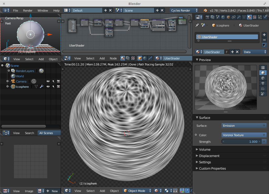
More along these lines actually…
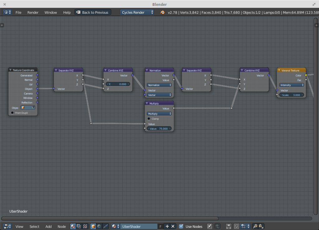
https://blenderartists.org/forum/attachment.php?attachmentid=385598&d=1434984007
Setup two generators, one that textures the cylinder perimeter correctly and one that textures a flat disk (cylinder cap) correctly. Then you need to assign one to the z normal and the other one to non z normal. Depending on the object, you may need to control the transition (sharp or soft, where it happens etc). Going from cylinder to disk is just a matter of exchanging two of the coordinates.
Mapping a seamless texture should be straightforward. Making a procedural generator with cylinder mapping (crossover 0-1 or 0-2*pi depending on how you look at it) seamless, is quite painful. I have some info in this thread:
https://blenderartists.org/forum/showthread.php?278285-Yet-Another-Thread-about-Cycles-Materials/page30
Mixing two xy generators by a sawtooth z this way works good enough for noise, but voronoi would produce visible shifts in density (half is fully one or the other, other half is mix of the two).
I believe Skorupa had a method of doing it in a spiral way which avoids this blending and would work ok with voronoi as well, maybe others can find a link? Btw, both would be anisotropic, end caps would be radially anisotropic and sides would be linear anisotropic. If this is an axel machined by lathing, imagine the feed of the tool capping the end would actually look like a spiral, and on the sides would look like very dense threads.
If we had repeating pattern generators this would be trivial.
If we had 4D pattern generators this would be somewhat easier.
Something to keep in mind: If using UV based tangents (required for proper look on the teapot snout/handle), anisotropic shading doesn’t smooth properly over the UV seam.
Here is a setup that might work:
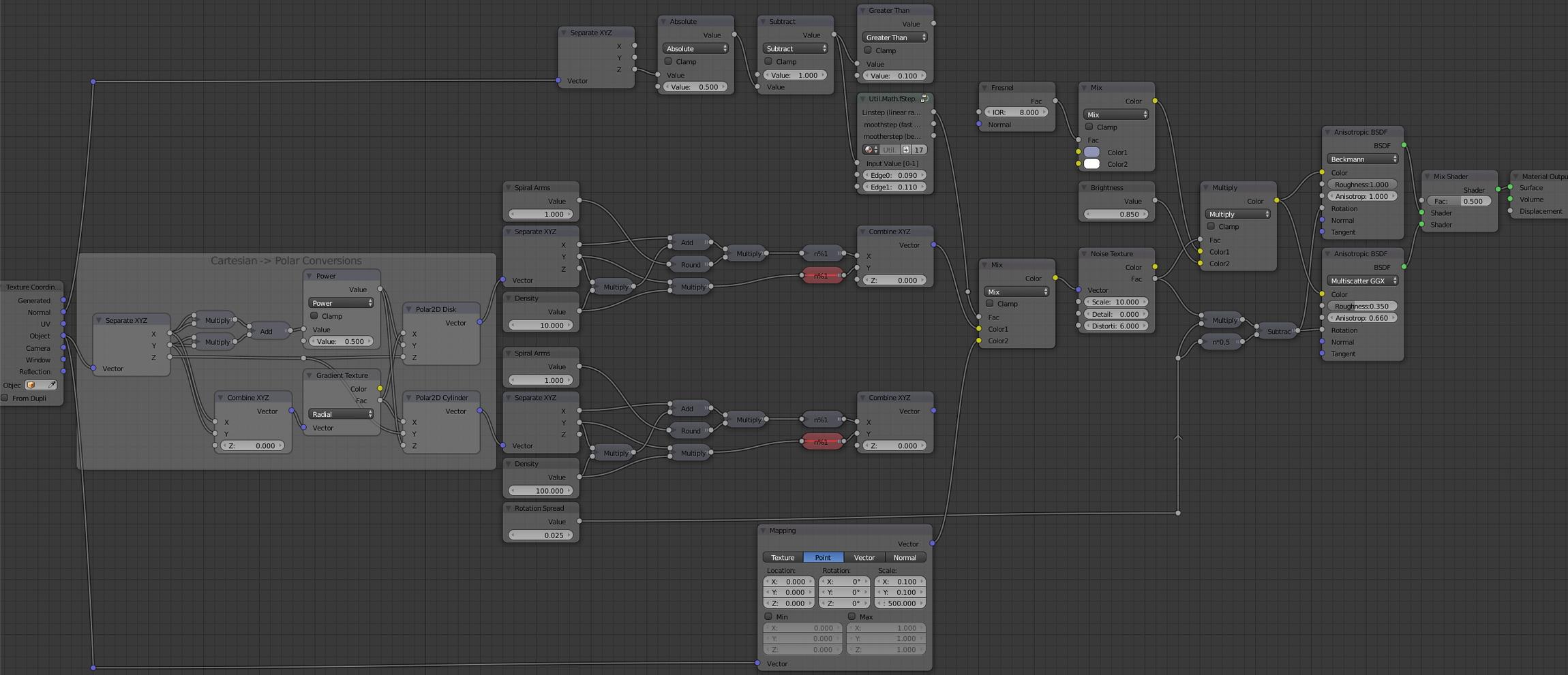
It has the following:
- One single generator, which in addition has detail 0, so should be efficient.
- Two coordinate types split by z normal; disk and cylinder or disk and parallel.
- Using disk (z normal) allows the spiral form, and visible seams can be ignored.
- Using cylinder (non z normal) allows spiral form, but can have visible seams.
- Using parallel (non z normal) will not show an angle, but doesn’t have a visible seam.
- No fancy crossover/noiseblending stuff used.
- Depending on what you need, you can most likely choose to not use two aniso shader nodes.
- For repeating coordinates, unmute the %1 modes that I have muted.
- Can probably simplify the spiral controls (1 round multiply sounds senseless, but they are for flexibility).
- Disk and cylinder mapping can be very useful for non noise based, such as either image mapping or wave to add “threads” or “tool feed”, but I have very bad experiences with moire when using dense wave for this.
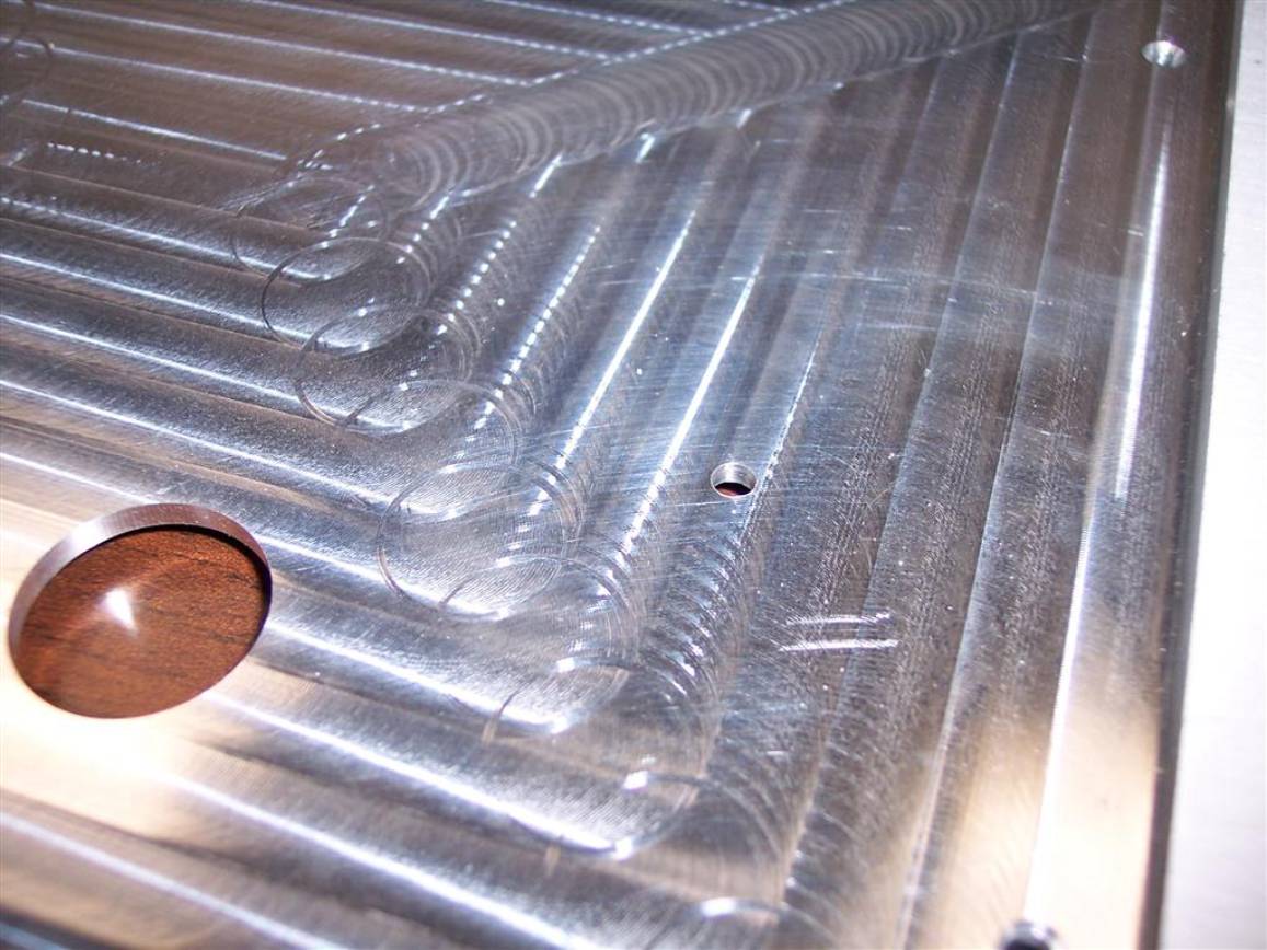
That one is more for controlling tangents for a visible sized tool such as milling. With a lathe you’d only get visible grooves, not the pattern left by the tool since the tool itself doesn’t rotate, see Lathe Example and Mill Example.
This one is more about how to achieve a relatively constant lathe feed appearance, looking similar on an end cut as on the side cut. In this specific case, something that doesn’t look too bad when applied on a sphere.
This is the look I get:
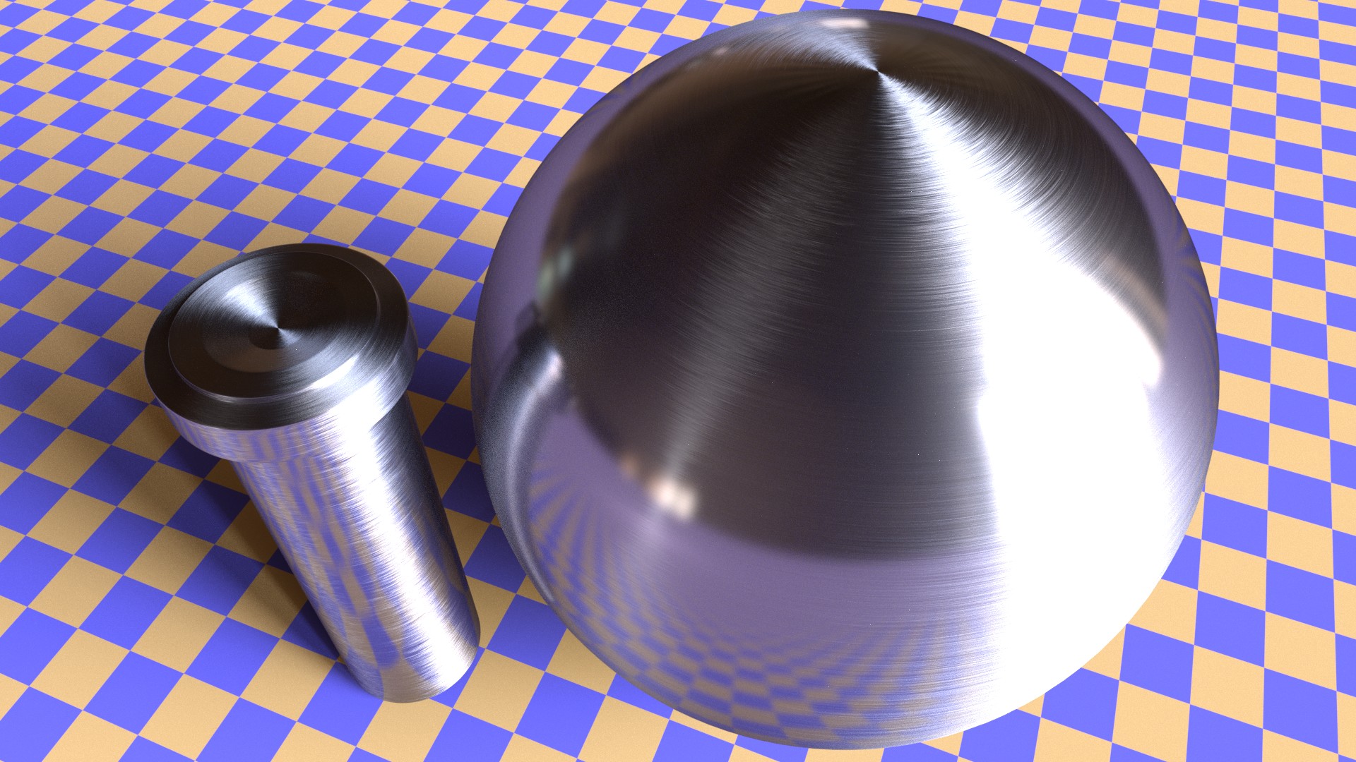
from this blend file:
http://pasteall.org/blend/index.php?id=44467
(slightly changed from the image in #5, no custom node groups).
Again, probably don’t need two shaders to do it, so delete what you don’t need.
Holy crap, thanks everyone… Sorry for such a late reply. Got a job, and have working with my client a lot lately.
Was asked to re-upload, but here is a file attached here instead - hopefully it doesn’t get removed and hopefully it isn’t too big:
Aniso_Example.blend (2.6 MB)
This is a 4k render of the file:
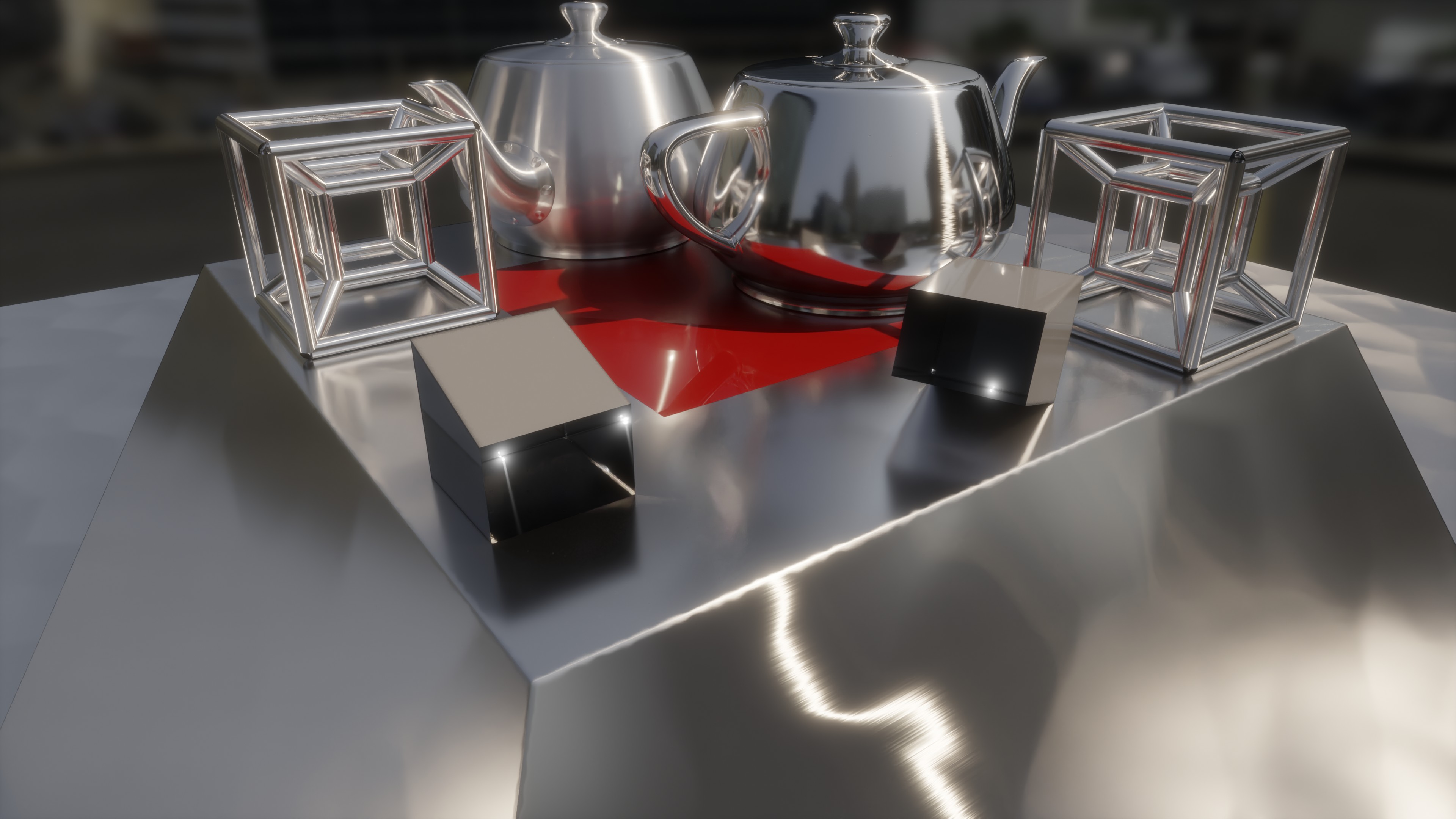
The description, also included in the file as a text block:
SpecReductionForClearcoat:
As name suggests, when a material is coated in a way that creates a shared interface (epoxy on top does this, a sheet of glass does not), the substrate IOR is lowered. You can test this for yourself with a plastic objects with tiny bumps on it. The glossy of the plastic makes the bumps visible, but when you pour water over it the reflections are almost nullified. With Principled shader, this is accomplished by lowering Specular when you add the topcoat to a dielectric material. Coated metal does not have this effect to a visible degree due to its very “high IOR” (it’s a bit more complex that that) in the first place.
AnisoGrazing:
Materials with highly anisotropic shading properties, such as regular brushed sheet metal, becomes mostly isotropic at extreme grazing angles. But even at these angles, some anisotropics are still visible. The change happens between extreme angle and very extreme angle, so due to the cost of mixing in glossy, this may be omitted completely in most cases.
PipeAniso:
Here anisotropic shading is used to create the extremely long tail found in some metals, even if they don’t have the surface grooves that makes them actually anisotropic - so consider this a hack. Very strong light sources such as the sun or surface of a spotlight is affected more than weak sources - or rather, the effect is more visible. You can do this for any section that consists of quads only. A pipe with a tee/wye would be harder to get right, I typically mix in a locallized glossy only shader in the split area.
AnisoInvariant:
Can be used to help long streak shading if the model/texturing doesn’t create enough of it. Invariant means that the response doesn’t change as you rotate the objects, the streak always go toward the lightsource. This is due to using geometry/incoming to define the tangent. Think of reflections on a water shore or tail lights reflecting off a wet street at night. The opposite (90 degree rotation) I have never seen in real life.
The invariant has a preview output if you want to see how seamless U generator can be used.
AnisoCube:
The pyramid shows how a typical appliance sheet metal (kitchen hood etc) might be setup. Shading wise it’s only an anisotropic mixed with a glossy to create the hazy effect.
Hazy gloss: https://jov.arvojournals.org/article.aspx?articleid=2630339
In addition, due to manufacturing and sagging, these surfaces are never 100% flat, but have patches of flat areas that are slightly off in normal. You can also use this normal as a base to add additional surface normal inperfections. Also, I use remapped noise to drive bevel width, using a quick add UV coordinate hack to make the object coors non-symmetric.
www.youtube.com/watch?v=nAcKLTtN8V0&t=13s
AnisoTeapot:
Beckman based aniso for semipolished, and GGX based aniso for rough, both using microroughness to drive the glossy haze element, but on the rough one it’s contribution is kept low. GGX is unsuitable for highly polished yet strong aniso characteristics. Whereas Beckman is only suitable for this. Most times, you should be using GGX. Using Beckman completely on its own, is not recommended, unless you have a superpolished appearance where strong aniso properties can still be visible (usually in the end stages of polishing).

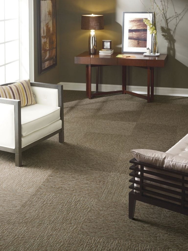
I also show how you must add 0.25 to aniso rotation when using Principled. But I really don’t like the result from this when staying in “plausible” ranges. You can still use this for very low aniso effects, such as quarterturned fabric tile flooring with a directional pattern.
Note that I’m only using a U seamless generator to modify the rotation angle in all of these, to show what can be done to modify shading in isolation. You may want to use a looser one of these to drive coloration and roughness, although I’d stay away from using it for bump as the scale this happens at is simply too small.
2 Likes
Hello CarlG !
I’ve been looking for a solution to this problem for a long time, and your proposal seems the only one that looks great on cylinders… unfortunately the ‘pasteall’ link seems dead… could help me please ? It would be perfect for my engineering renders !
Or is the Aniso_New preview the corresponding node tree that I could reproduce ?
Thanks in advance for your feedback and have a nice day !
Best regards,
Thomas
Since the arrival of 4D generators, I’ve updated it to support UV -> Seamless U using 3D generator and UV -> Seamless UV using 4D generator. So that flip&mix approach is no longer needed. Note that this uses UV direction and spacing to drive the generator, and UV direction to drive the tangents. Therefore you can’t make “proper topology” cylinders, but have to collapse to center like we used to make cylinders. Which is perfectly fine for my needs, so I never bothered trying to bake tangent maps and blend in different approaches. Attached is a teapot with seamless cylindrical generator to drive rotation, you may want to let it drive color, roughness, bump or whatever. It’s slightly off, I think it’s seamless for even numbers only, I forgot to fix that.
anisotest_cyclesonly.blend (988.9 KB)
1 Like
I tried to apply the material to another object and it rendered black
is there a trick to use this mat ?
pot seems to render fine !
thanks
happy bl
No trick. As I said it needs proper UVs for the tangents, and setup to fill the U direction for the seamless to work. If you have a problem with a file, then share it.