but that leaves us with horrible artifacts at the corners, plus, as I understand it, creasing is not well supported when exporting, therefore I would prefer to avoid it all together.
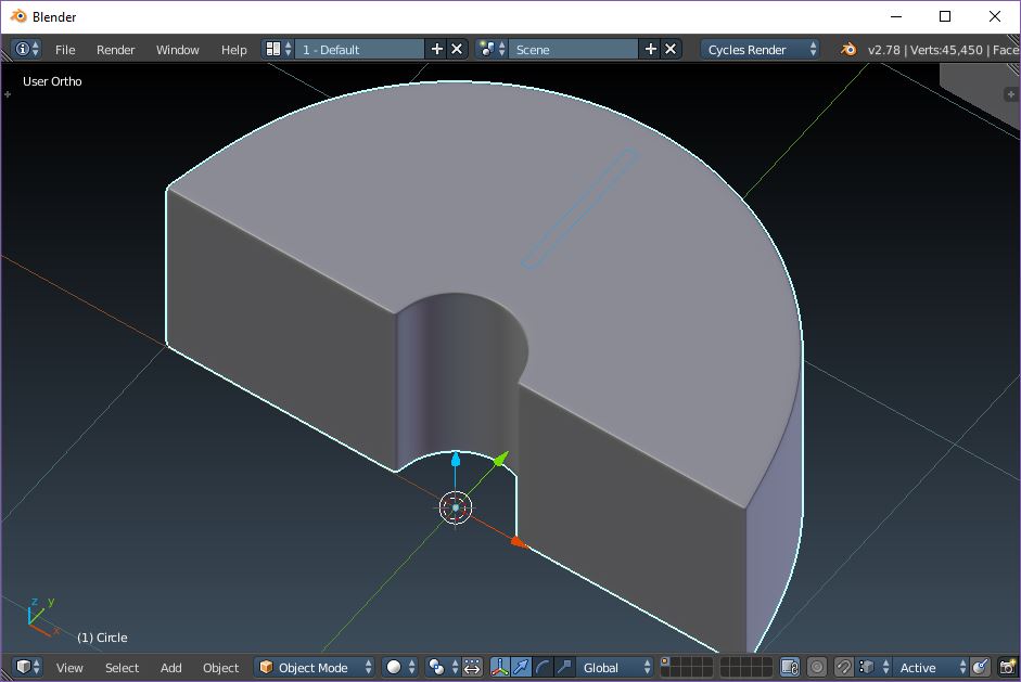
This creates a very clean hole without artifacts from stretching. However, the distribution of loops that make our half-circle is not equally distributed anymore. The top is therefore flatter, and the shape is not perfectly round anymore
Thanks to both of you for taking the time to do this. The method proposed by JA12 is basically perfect, exactly what I’m looking for. No creasing, no ngons, very sharp corners, no artifacts.
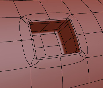
As I understand it, the supporting edges work well in this situation, because even though they are not evenly distributed and create some poles, they’re all on the same plane (on flat surface). But for the sake of perfecting my topology knowledge, how would one do the same thing on a subsurfed torus, for instance this:
Let’s say I want to extrude in that selected face inward (a square hole with sharp edges), again only with supporting edges (no creases). Are ngons becoming necessary in this case? If so, is there a way to place them so they don’t create artifacts/bumps or deform the doughnut shape?
With the torus you need more base geometry. Extruding a single face will subdivide to a simple ellipse. To get the saddle shaped hole you expect on the torus you need to extrude at least four faces.
Yup. The issue is that rounded surfaces need similar face size and if it has to change, the face size should gradually change. Otherwise you get a sharp detail like with the control loops on hard edges. Subdivision surface approximation pulls the surface along the edge loops and any deviation in face size means the edges aren’t evenly spaced, so the subdivision result won’t be even.
Starting with more geometry helps because subdivision surfaces makes smaller change in the surface curvature, but doing that on a curved object because of small detail isn’t great because one of the reasons we’re using subdivision surfaces is to avoid doing that. The result will be a compromise.
You can most definitely help subdivision surface by making the face size change gradually
which might also mean adding more geometry to start with.
What kind of surface defect is acceptable depends on what you’re doing and the result you want for that, for example optimizing surfaces for reflections could be a thing http://aliismail.com/tutorial_car_modeling.html
so you might need to change how you make the surface or use tricks to hide the surface defects that the subdivision creates. Separate geometry or not using subdivision surfaces at all are also options to consider when solving a modeling problem.
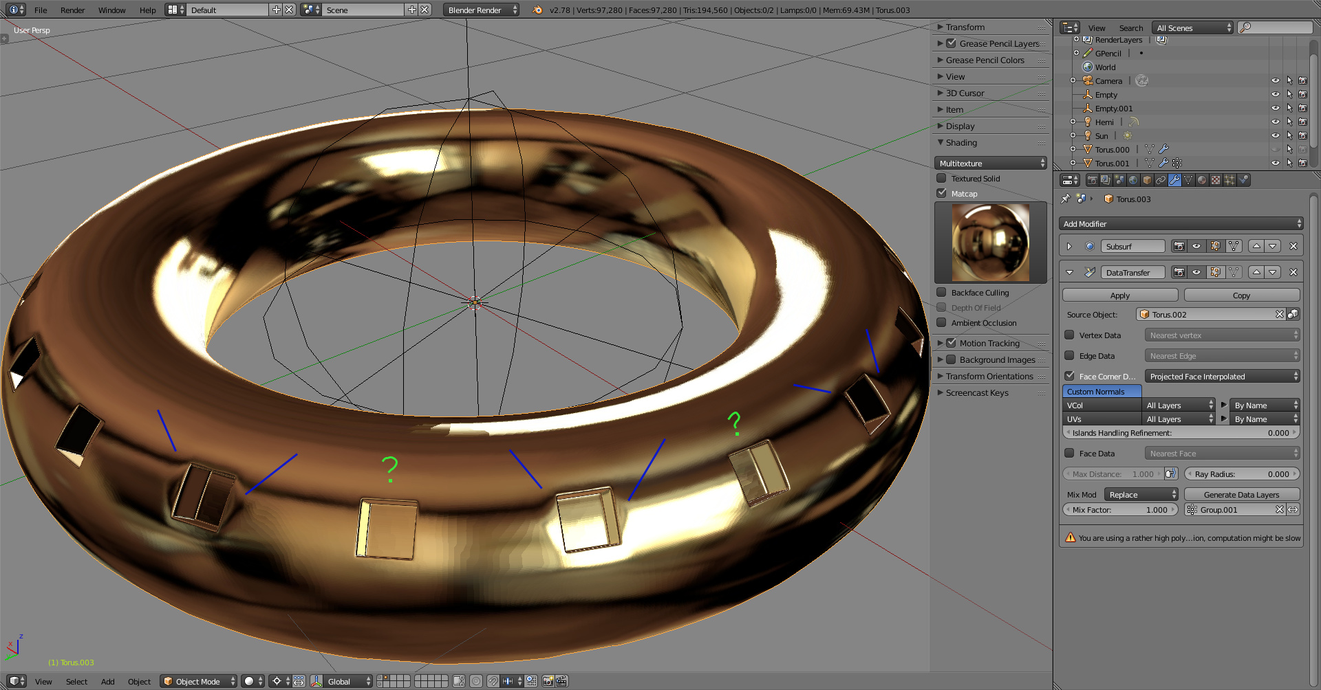
Here I’m using a bit more geometry to be able to build the control loops for both details and then transfer normals from another object to help clean the reflections and hide the remaining surface imperfections. The source for the custom normals is a high resolution torus without the details.
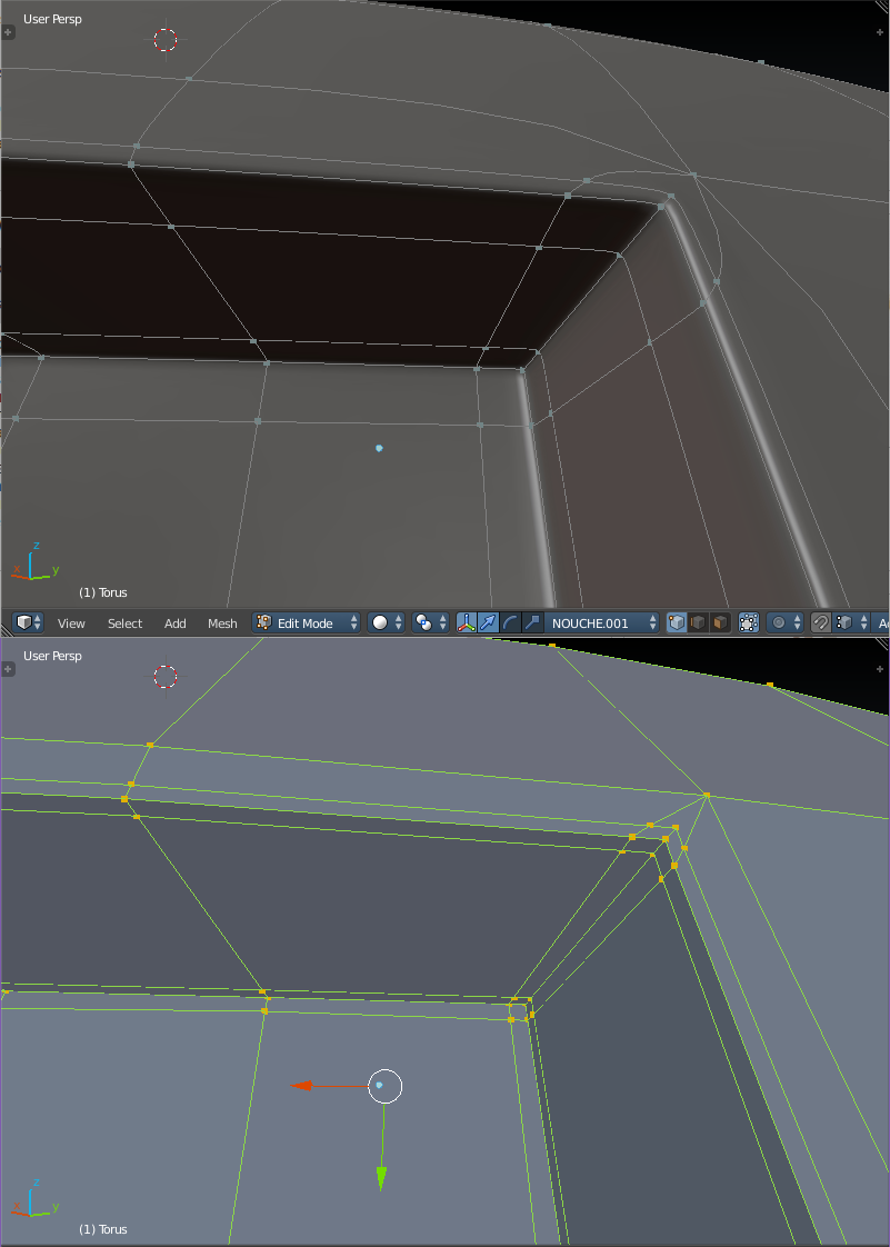
It took a while to figure out what was the exact topology of the corners and how both of your methods differed, so I replicated them myself and made these clearer pictures for anyone who might read this and have this problem.
I understood that both methods are basically the same and differ only in the way that supporting loops connect to the mesh (through which vertices the loops are routed). I prefer JA12’s method for it is more evenly distributed, with 8x 5-sided poles instead of 4x 6-sided and 4x 4-sided poles, with consistently more even quad size and distribution. This results in less artifacts, which are especially visible around 6-sided poles.
Thanks to both of you for such great answers, I hope this benefits others as well.
Also, I didn’t succeed in using the data transfer modifier, it didn’t make any difference. The source was a highly subdivided torus (applied Subsurf x3) located in the same position (but hidden). There was no visible difference in edge reflections when turning it on or off. I didn’t consider an issue because although it was useful in this circumstance, I couldn’t really see how using this technique on more complex objects would work (other than applying high-res normals on low-res meshes, but isn’t that what baking normal maps is all about?) Unless I didn’t really understand what that technique was about…
Which made me think, is there a way to paint directly on a normal map to erase those artifacts that might show up when using uneven topology on a subsurfed mesh? Is that sometime that is usually done for this purpose? Or is there another good way to edit normals to get rid or them?
“It doesn’t work” is not enough information to work with to help you find out why. There must have been a problem and it’s in your file, or it’s a graphics problem.
Try this one. Second scene layer has another torus that fixes the minor shading/reflection issue on every other column of square indentations. subdivision_reflections_datatransfer_ja12.blend (319 KB)
To recap, the result subdivision surfaces give you is not perfect for everything. Small details on a curved surface is an example which makes you fight against the advantages subdivision surfaces give you because those details need geometry for you to control the subdivision on them too.
More control geometry on a curved surface means adding it on the whole surface, not just where the detail is (unless you can do a loop reduction), which means smaller angles between polygons along the surface and less need for subdivision. And even when you do that it might not be satisfactory enough for some purposes, like having uniform reflections on a surface that subdivision makes uneven.
I added data transfer modifier to use custom normals and fix the issues on a high polygon model. Might not want to use that for a car body but fixing a perforated chrome detail for a close up shot should be fast and easy enough.
Normal map is a difference of the directions two surfaces point at. Or in other words, information that is needed to make the surface it’s on to look like it has details from another surface. Bake one surface on itself and there is no difference. Two parallel surfaces, no difference. When surface direction change along the normal of the original surface point, then there is a difference and bake result would give something else than the default values on a pixel.
Could use it to change the appearance of the surface on high polygon object but usually done to fake detail on a much lower polygon one, baked from object to the other. If there is an issue in the high polygon object, custom normals is again an option to fix the issue and then bake.
It’s data, not color, so you can’t take any paint tool and just paint on a normal map image. No one is stopping you but really shouldn’t try to fix a detail on a normal map like that because the brush has no idea of the two surfaces, it just mixes RGB values in the brush with the ones on the image.
I see. I had a few misconceptions, I think. I thought the source object had to completely encompass the target object, so I didn’t see how it would be practical on complex objects. But if you can use a source object which is equivalent to a local fraction of the target to transfer normal data, then that makes much more sense to use this method for covering artifacts.
My understanding of normal maps was that they were containing the absolute values for the normals. Now that you mention it, that makes absolutely no sense: it would make objects look the same from whatever angle you look at them. Being interpreted as relative to the tangent, I see how they would be impractical to correct shading on the base mesh. As always, thank you for you time, this was very informative!