Hi all,
I’ve been working on an addon that smooths an edge loop of a mesh. This would usually be the outer/border edge loop of your mesh. This loop should be closed (!), and it’s also kind of assumed your loop delimits a convex shape. There are also some other assumptions, which we can come back to later if needed – this is a WIP. Conceptually, this is a 2D operator, but you might get away with some 2.5D uses too, if you know what you are doing.
I should probaly make a video explaining how this all works, but until then, let me just try to explain it in a very lengthy text. Also, this may already exist, so you can stop reading now if you know it does. Feel free to let me know, though.
smoothEdgeLoop-20170110.zip (5.59 KB)
- General idea:
I originally wanted to make a circle with good topology. The standard topology of a circle (or sphere, for that matter) is annoying, because it usually involves ‘poles’, which are vertices where a lot of faces/triangles come together. So like the IcoSphere primitive tries to avoid these poles in a sphere (using triangles), I wanted to avoid them for a circle, but using quads (because I’m weird that way). So the idea was to have a (central) quad to start with, and then extend that outwards, using the well-known 1-to-3-edges topological transformation (see image below).
However, it appeared that the tools/algorithms to do this, could easily be extended to any (‘reasonably-well-behaved’) polygonal shape. So I added some more parameters and made this work with any selected edge loop. This should really be implemented as a modifier, but that unfortunately is not possible using the python API (see here: https://blenderartists.org/forum/showthread.php?413406-Writing-a-custom-Modifier). So we might come back later to how this is actually presented to the user.
- Install and use:
I don’t think the installation works using the ‘install from file’ method. You should manually put the python files in a folder you created, eg, on win7, something like “C:\Users\YourUserName\AppData\Roaming\Blender Foundation\Blender\2.77\scripts\addons\smoothEdgeLoop”.
To use it, you need to be in edit mode and have at least 3 mesh edges selected. As mentioned, the loop should be closed, and the addon will probably crash if it isn’t. You can then add-mesh (shift-a) the ‘Smooth Edge Loop’ geometry. Since we’re in edit mode, it will automatically be added to the selected mesh, which is quite interesting (see link about modifiers above). You may want to ‘remove doubles’ on the resulting vertices, btw.
- Settings/GUI:

From top to bottom, there are 4 blocks of settings. The top row allows you to reverse the order of the loop, as the edge directions may vary depending on the underlying/neigbouring faces. You can see the effect on the normals of the generated faces. You can also choose to not generate the faces, in which case you’ll have the option to generate the edges. Caution!: if you then uncheck the ‘Add Edges’ option, the addon GUI disappears. ATM, I don’t really know why this is, so you might not want to do this. I’m guessing Blender doesn’t like meshes with only vertices; if this is the case, I will remove the option to not have edges.
The other 3 blocks (1: Angle & Offset, 2: Guide construction & Outer Verts Slide, and 3: Inner Verts Project) drive the implementation, see below.
- Implementation:
4.1/3: Offest/extrude loop vertices
For each vertex in the edge loop, generate an offset (outward) duplicate. The actual offset depends (linearly, ATM) on the (inner) angle at said vertex. If the angle is at it minimal value, the offset is at it’s maximum, and vice versa. This dependency is there to try to minimize the difference between the original and the smoothed shape. The min & max values of both the angles and offsets let you define that line. The direction along which to offset would usually be the bisection of both edge directions, but you can bias this to either edge direction using the ‘Bias’ parameter. ‘Scale’ just applies a global factor to the calculated offset, which we may need later – eg, as we add other (non-linear) functions for this dependency.
4.2/3: Generate 2 outer interpolated vertices:
Given the offset loop calculated above, we can generate a tangent direction for each offset vertex. We can then calculate the intersection of these directions for each edge, which gives us a first estimate/guide of where the interpolated vertices should be. We will then offset this initial guide inward a given ‘Factor’, towards a target on the line segment between the offset vertices. You can adjust the ‘Bias’ to favour any point on this segment. The outer 2 vertices are defined by sliding a vertex between the offset vertices and the guide generated earlier. You have ‘Bias1’&2 to control these slides.
4.3/3: Generate 2 inner interpolated vertices:
Given the outer interpolated vertices calculated above, we can generate 2 more vertices, which should be closer to the original edge, so we can ‘project’ them onto to that. You can adjust the projection distance using the ‘Factor1’&2 parameters. The lengths of the segments on the original edge are proportional to the lengths of the corresponding outer edges.
Here are some drawings illustrating the construction process:
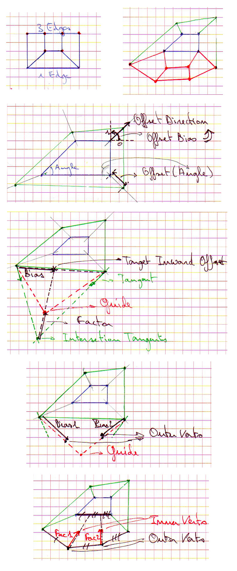
There are 5 rows in this image. On the top row you see the 1-to-3-edges thing and the result (in red) for the bottom edge of the original/blue edge loop. Offset vertices are in green. Row 2 shows the generation of the offset vertices (step 4.1). Row 3 shows how the guide is constructed, which is then used to generate the 2 outer vertices (row 4, step 4.2). On the bottom we calculate the final 2 ‘inner’ vertices (step 4.3).
Please note that I’ve made some small changes to the GUI after I made the images. Eg, ‘Guide construction’ used to be called ‘Inward Projection’, and there may be others.
So there we go, have fun with the addon and let me know what you think!
g