extrude on 2 rails, possibly via script?

I have 2D aerofoil profile, which I’d like to extrude alnog a path. The Profile should not only be translated and rotated (the wing is bend), but scaled (a different chordlength alon the path).
Here are some illustrations:


(2D cut at dirrefent wing sections)

(partly lofted; finally, the whole wing should be one solid object)

I have a function (in the mathematical sense) which gives me the enclosing curve (the black lines in the images).
There is the extrude along a path. What I would need is, given the leftmost 2Dprofile in the first picture, and the tail and tip paths -> extrude along these ‘rails’.
Another option (at least in freecad) would be loft through given faces.
My final goal would be to do this from a python script.
What would be the best approach in blender?

edit:
in opencad comparable functionality is documented as ‘linear extrude with twist and scale’ here: https://en.wikibooks.org/wiki/OpenSCAD_User_Manual/Commented_Example_Projects

on way
if you have 2 profiles you a use the bridge edge tool in bl
also available in looptool addon

not certain about other things !

you can use a script to make a profile
but then how to add along a given path with right rot and loca ?

happy bl

HI,
sorry for the late response.
I tried the loop tool, but I’m not really happy with the result:
This is the top-view of the 2D profiles (similar to above)


I played with loft an get something like:


which is still non-continuous at thepositions where the profiles have been (it looks much like linear). If I increase the sthength, the curves in between get mor bumpy (between the given profiles), but still non-continuous there (as can be seen on the right edge).

I would expect an edge more like this (awfully hand-drawn):


-> something smooth like fitting a bezier through the outer profile points.

Am i doing something wrong?

I could use a lot more profiles placed at the correct locations, but still, the loft result would be like many linear loft results, which is quite unsatisfactory.
Any ideas?

did u check the curve extra tools
but no loft tool sorry!

may be try the Bsurface addon

this one has loft included in addons
http://wiki.blender.org/index.php/Extensions:2.6/Py/Scripts/Curve/Curve_Tools

if not then use a Nurbs surface and get smooth 3D surface

happy bl

I will have a look at the curve tools. Thanks.

I have an analytical curve for the trailing and leading edge -> in principle, I could generate a very dense point cloud.
Why not creating a ‘smooth’ mesh directly from a point cloud?

depends what you want to do !

for very smooth surface then use the Nurbs surface
and easy to change the shape
or use the Curve tools which has something equivalent
but not necessarily equal to Nurb smooth 3G which is probably the best and smoother one!

happy bl

hmm, I had a look at nurbs surface curves and nurbs surfaces.
The problem I have is that I could set control points e.g. like discussed here: http://blender.stackexchange.com/questions/7020/create-nurbs-surface-with-python
However, the curve will not go through the points.

Isn’t there a way to have e.g. a point cloud from a surface scan, and then fitting a (nurbs surface) through those points?

Any help appreciated!

edit:
finally, I would like to use the resulting surface in blender-CAM for cnc milling. Will this result in a smooth CAM surface?

you can use points cloud and skin it
but not certain it will be smooth !

also Nurbs are supposed to pass through the original points as i remember!

what kind of 3D model is this ?

can you show some pic !

happy bl

also Nurbs are supposed to pass through the original points as i remember!

any idea how to find a hint about that? I have been searching the web for 2h now, but could not find something…

The model is the one shown in the first post: 2D slices of airfoil data; I know where I want to have which scaled/rotated slice in 3D space, and a smooth surface through them.

I attach a blend file having 4 of the 2D profiles located in 3d space (the one i made the loft test with)
h105_2d_3dSpace.blend (447 KB)

there is a script to make foils shape
did you test it ?

Nurbs or spline are made with spline curve
so if you don’t change the weight it should pass through the original data
spline are supposed to be collocial polynomes or something like that
see Wiki on splines and Nurbs

will check your file

Edit
did you check the surfaces skinning with Splines curves
for boats & air planes

it should give smooth surfaces

happy bl

The main problem I see here is that you have way too many vertices on the profile for the number of vertices you have in between the profiles (none in your case). So look at these images:


These are views without the Sub-Surf “Optimal Display” turned on, I set the level at 3, the one below is the mesh:


Note the number of vertices in the profile - each profile is rotated about the leading edge at 2, 6, 10 & 12 degrees in the Y axis from the outside inwards - note the curved leading front and rear edges. This is possible because the polys have a far better aspect ratio than yours. With the number of vertices you have you would need way more profiles to get a good poly aspect ratio, and therefore a curved connection between points on the profiles. I too have no points between the profiles, but I am allowing the Sub-Surf modifier a decent chance at smoothing the wing due to the poly aspect ratio. The Sub-surf cannot smooth outside the smallest dimension of the poly, as your polys are so narrow, you cannot get a smooth front, or leading edge, or inter-connection edge.

Otherwise - you will have to model precisely and at great detail, with curves I think.

Hope this helps you.

Cheers, Clock.

EDIT:

If you want your final mesh to look like the first two images, just click “Apply” on the Sub-Surf mod, but don’t do this until you are sure of the shape…

Hi Clock,
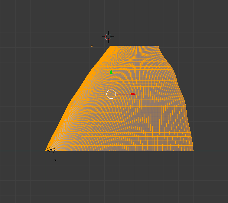
good point with the aspect ratio.
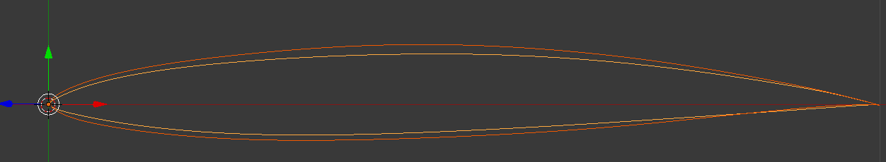
So why do I have so much points on the 2d profile so far:
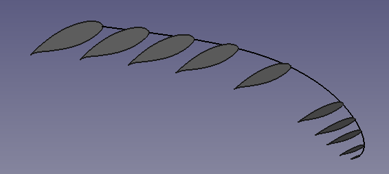
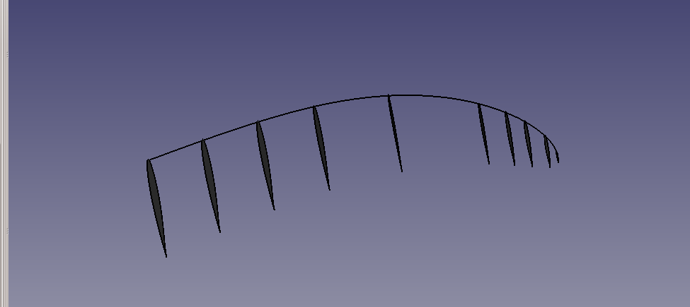
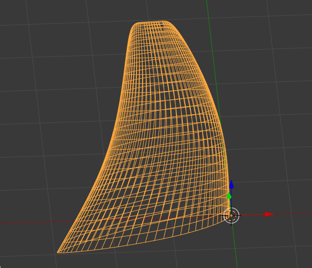
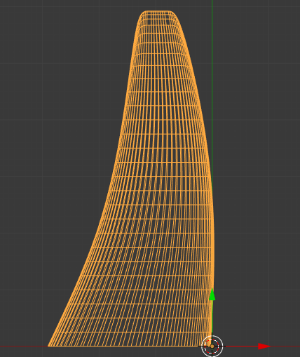
I fit a nurbs curve from points (code below). The the resulting nurbs curve however does not exactly pass the points (can i enfoce this somehow?). Therefore, getting curves from a set of points and a subset with half of the points results in a different profile.
-> how should I get a curve passing exactly through the given points (from python), such that the results for the two curves are similar?


import bpy
import math
import numpy as np


def curveFromPoints(coords,name,tClosed):
    # create the Curve Datablock
    curveData = bpy.data.curves.new(name, type='CURVE')
    curveData.dimensions = '3D'
    curveData.resolution_u = 2

    # map coords to spline
    polyline = curveData.splines.new('NURBS')
    polyline.points.add(len(coords))
    for i, coord in enumerate(coords):
        x,y,z = coord
        polyline.points[i].co = (x, y, z, 1)

    if(tClosed):
        polyline.use_cyclic_u = True
    
    # create Object
    curveOB = bpy.data.objects.new(name, curveData)

    # attach to scene and validate context
    scn = bpy.context.scene
    scn.objects.link(curveOB)
    scn.objects.active = curveOB
    curveOB.select = True

#----------------------------------------------------------------------------------

def h105Coords(tFine):
    if(not tFine):
        hCoord=[(1.0000000000,-0.0009960075,0.0),
                (0.9923910747,0.0008730353,0.0),
                (0.9732261933,0.0061049655,0.0),
                (0.9028826756,0.0228094365,0.0),
                (0.5656912247,0.0715014889,0.0),
                (0.1135761203,0.0489492481,0.0),
                (0.0035325422,0.0069703941,0.0),
                (0.0000000000,0.0000000000,0.0),
                (0.0109729439,-0.0106883099,0.0),
                (0.2435759130,-0.0497218477,0.0),
                (0.8109499838,-0.0136364597,0.0),
                (0.9842246660,-0.0002785008,0.0),
                (0.9960683709,-0.0007296290,0.0)]
    
    else:
        hCoord=[(1.0000000000,-0.0009960075,0.0,),
                (0.9968850158,-0.0002131417,0.0,),
                (0.9923910747,0.0008730353,0.0,),
                (0.9841079235,0.0032235503,0.0,),
                (0.9732261933,0.0061049655,0.0,),
                (0.9494646214,0.0120285280,0.0,),
                (0.9028826756,0.0228094365,0.0,),
                (0.7465577106,0.0520873754,0.0,),
                (0.5656912247,0.0715014889,0.0,),
                (0.3662695884,0.0746947582,0.0,),
                (0.1135761203,0.0489492481,0.0,),
                (0.0228438073,0.0207011579,0.0,),
                (0.0035325422,0.0069703941,0.0,),
                (0.0000000000,0.0000000000,0.0,),
                (0.0109729439,-0.0106883099,0.0,),
                (0.0555936001,-0.0264323653,0.0,),
                (0.2435759130,-0.0497218477,0.0,),
                (0.6224089664,-0.0347331559,0.0,),
                (0.8109499838,-0.0136364597,0.0,),
                (0.9368195370,-0.0013936882,0.0,),
                (0.9842246660,-0.0002785008,0.0,),
                (0.9960683709,-0.0007296290,0.0)]
                        

    return hCoord        

#---------------------------------------------


hCoord=h105Coords(False) #tFine
curveFromPoints(hCoord,'h105fine_2D',True)

Post me a set of coordinates for the profile and I will take a look. How many points are you working from, where is the profile coming from, why are you using NURBS curve? A set of points created as a mesh edge loop with a sub-surface applied might be much better, particularly if you use a small number of points.

The mathematical definition for a NURB (Non-Uniform Rational B-Spline) curve dictates that the curve will NOT go through at least some points if that disturbs the exponential defining algorithms of the NURB curve. The problem is that if you cut a NURB curve in half, even at a control point, you will not necessarily get two curves that look the same, as a contiguous shape, as before the cut, I know it should, but it won’t always.

It may be better to revise your methods, rather than try to solve a problem that seems determined by you using NURB curves rather than edge loops and sub-division modifiers.

To illustrate my main point, look at the two object below:


The one of the left has two polys rotated apart, the one on the right was copied from the first then I sub-divided the end edges to 4 cuts - see what it did to the shape of the profile- totally messed it up by trying to add too many vertices… wrecked the subsurface smoothing… Not what I wanted.

Cheers, Clock. :slight_smile:

Sub cannot make a high precision surface only Nurbs can do that !

may be use the Nurb spline and skin it like a boat shape!
see Bl wiki on skinning surface with Nurbs

https://wiki.blender.org/index.php/Doc:2.6/Tutorials/Modeling/Surfaces/Skinning

This is why CAD are using Nurbs so much
it is high precision work done with Nurbs curves or surfaces
which cannot be done with subsurf as I know of

happy bl

Then its down to using NURBS and more profiles I think… Much depends on what the end goal is - Blender is not a CAD tool - so maybe OP should be using FreeCAD or similar to produce what he wants other than visualisations (is that a word?) and animations. I really need to see the coordinates to check how accurate the sub-surf would be - hence why I asked for them.

Good point well made Ricky! i am going to checkout your link.

Cheers, Clock.

EDIT:

So I have remade my wing using the NURBS surface technique - very nice it looks too, but he points aren’t on the curve… I need to investigate further to accurately control the curve.

Also I am finding it difficult to get a method whereby i can use by existing mesh profiles to convert to a NURB Surface object, or a method to use the profiles from the mesh object in a NURB surface, does anyone know how to do this?

Cheers, Clock.

we don’t have anything to convert mesn to Nurbs in BL yet but does exit in some other soft !

show some pic why it is not fitting as shown in wiki for nurbs
it should follow the points precisely !

not certain if doing it with script change things but I might test it for fun

happy bl

I ran the script and it looks like points are exactly where they should be
but surprise that you get down below 1 mm
not certain how come ?
that is not possible as I know of !

why do you say it does not follow points ?

now you don’t have a lot of points in the center

and another things is that I don’t think this is the right kind of curve to be use for Spline nurbs !

Did OP tried the Nurbs spline as shown on wiki page
this is doing auto smooth

thanks
happy bl

have not tested in a long time

but here is example for spline curve


import bpy
import mathutils
from mathutils import Vector
from mathutils import *
 
 
cu=bpy.ops.object.select_by_type(extend=False, type='CURVE')
print ('List of curves  =',cu)


def splineType(Curve):
 print (' my   Curve =',Curve)
 curveType = Curve.data.splines[0].type
 return curveType
 
obc =bpy.ops.object.select_pattern(extend=True, pattern="Curve", case_sensitive=False)
 
 
splineType(obc)


###
 
def createNurbs(verts):
 
 print("creating new NurbsCurve from verts
")
 scene = bpy.context.scene
 Nverts = []#
 for v in verts:
  Nverts.extend(v)
 curve = bpy.data.curves.new("NurbsCurve", type = 'CURVE')
 spline = curve.splines.new(type = 'NURBS')
 spline.points.add(3)
 spline.points.foreach_set('co', Nverts)
 print("len spline pointss",len(spline.points))
 
 for i,point in enumerate(spline.points):
  point.co = verts[i]
 #error   spline.endpoint_u = True
 newCurve = bpy.data.objects.new("NurbsCurvePKHG", curve)
 
 #### link into scene
 scene.objects.link(newCurve)
 newCurve.select = True
 scene.objects.active = newCurve
 
 
#   print("returning: ", newCurve.name, "

")
 return curve
 
verts = [[1,2,3,1],[2,2,2,1],[4,5,6,1],[0,0,0,1]]
createNurbs(verts)


happy bl

NURBS might not be the way to go with this particular software. (Bsurfaces is about as close as you’ll get, as the official NURBS are pretty limited.) But if you’re just wanting an airfoil surface with a smooth transition for something like 3D printing, it’s still quite possible with a polygon mesh. It just involves subdividing until you get to the level of smoothness in surface transition you desire. After print you’d still have to sand or do acetone treatment to smooth out the plastic components.

As for the tricks I know in getting a blended wing?

If you want to stick with bezier paths, the airfoil shape is your bevel profile. Also the set centerpoint for that profile is where it’d center on the path for extrusion. Then on the bezier path you have the bevel profile applied to, you can use twist (CTRL-T) and scaling of the points (Alt-S) to further affect the shape. Keep in mind there’s not much transition in the overall foil profile, and point scaling doesn’t allow axis separation. However it does give an nice blended shape with decent control, and there are other smoothing options between the path points in the curve properties. This would also need conversion to a mesh for it to export properly.

Next option is to polygon model the wing out, and this has waaaaaaay more flexibility in regards to how Blender works. Basically you’re taking advantage of how Catmull-Clark smoothing works and Blender’s modifier stack. So you model out a basic wing into the profile, you can transition the profile between what I’d call the “baseline” extrusions. You don’t want too many though and you keep them simple. (I find making the airfoil profile from an 8 or 12 sided cylinder is usually good.) The base wing shape shoudn’t have too much sweep or twist from root to tip. Then you subdivide it once, and that should give enough mesh density for further modifiers to do their thing. And this is where it gets pretty cool. Lattice modifier is kind of ok, but I find a lot more control with a really generic wing shape over the main wing (made from 6 or 8 sided cylinder) and using mesh modifier. Then you put control loops across the control cage at stages in the wing before applying the mesh modifier. Then you have a whole lot of freedom to modify the twist, sweep, and scaling, that the usual proximity editing falls short with by editing the applied control cage. I know I could probably come very close (if not spot-on) to your desired wing shape using that trick. Then on top of the mesh modifier another subdiv modifier for final smoothing. I usually keep a copy of this setup on another layer or scene in the .blend if I’d like the option to do future changes, because for output you’d need to apply all the modifiers. Keep in mind that this is for creating polygon mesh objects that can be exported to .obj or .stl. It’s not NURBS.

If you look specifically for the .blend files for my SkyFry airplane at Thingiverse, I believe I still have some stuff on other layers that shows how that works. (Yes, I know it’s still a WIP. Just one of my ‘round tuit’ projects. But there’s a few neat things I was doing with it that might be interesting to share.) Another related thing at Thingiverse is my “swept wing rib sections” which might even be better yet. Yeah, I do free-form modeling with this stuff - however I could get it to match plans if I had that goal in mind.