I’m rigging a vehicle in Blender for the first time, my background is in Lightwave 3D (Still new to Blender).
I have the vehicle completely rigged and everything is working perfectly.
I used a combination of empties and custom object shapes to build the rig Plus, a few bones for a minor thing.
I was wondering if I’m able to convert the empties and custom shapes to an armature type rig, allowing me to
make proxies of the Meshes being animated.
Why didn’t you rig the whole thing with one armature to start with? Seems like if you wanted to Link this model to another blend file, that is what you should have done.
Having said that, I do not know of a way to do this automatically - maybe you have a longish job on your hands. Sorry I cannot come up with an easy method.
Hope all is well buddy. I was in the middle of doing that when I posted. This was the method I used in both LW3D and Maya. I found out the hard way Blender is a little different, lol! Like I said before, everything is working perfectly. It was when I wanted to Link/Append into a different scene, is when the problems started. I’ve already replaced some of the custom shapes, will keep posted.
Just a lot of cursor snapping and snapping stuff to the cursor if needed. At least that way you can use the existing empties as a positional reference when building your armature. Still a lot of grind-through manual work though.
The rig has been updated and is functioning perfectly, Yay! Plus, I was able to do more with less, which is always awesome. All that is left to do is to connect the mesh to the rig and do some Link/Append tests, will keep you all posted.
Hi David,
I recently also rigged a car with empties until I realized I should have done everything with bones, especially because it would have less rotation issues when exporting to fbx. also for proxies linking it’s better using bones.
however I wrote a script that adds an extra parent to each selected empty, and applying the intial location and rotation to the parent, so that it behave somehow like bones, it helped me a lot with the rig, especially for getting intial locations that are not on the 0
If you want to try it out, then I explained it on
The rig is completely updated and the Link/Append test was very successful. I’m currently looking into On/Off switch of an object via the Local space of a bone.
You can add a driver on both the Screen Visibility and Camera Visibility (RMB-Click the Eye or Camera icon on the Outliner and chose “Add Driver Manual Later Single”). Then edit the driver in Graph Editor (DriverMode) => Drivers Tab and set the var object to be the bone - if you then move the bone to 1 in any axis, and set the Driver Type to Scripted Expression and type var into the box, the value will be 0 when the bone is at rest and 1 when you move it to say Local X = 1. But remember 0 is visible 1 is invisible for these icons.
I’m not doing anything with the Camera Visibility. I am having success with the drivers but, I want parts of the vehicle position to be completely closed when the bone is at 0 and Opened at like -2cm.
OK, so you mean the doors for example? If so then you are using the new bone to open and close the doors? If not - tell me exactly what you mean…
If this is what you mean…
This can be done through Drivers or Transformation constraints. So for a Transformation Constraint lets say the door bone has to swing from 0 to 80 degrees about Z axis to open the door - the operating bone moves say from Local Y = 0 to Local Y = 2cm. The you would set the Transformation constraint to be; Target is the control bone, setup is Source-Location Y-min = 0 Y-max = 2cm, Source To Destination Mapping is Y = Z (So movement in Y of the Source effects Z of the Destination, Destination-Rotation Z-min = 0 Z-max = 80. You can click Extrapolate Checkbox (it matters not really). Then constrain the operating bone to move only from Y = 0 to Y = 2cm.
It’s harder with Drivers - mainly because these work in Radians not Degrees for rotations, but it is do-able:
When the bone moves from 0 to 2; the rotation is 80 degrees. To get degrees in a Driver you would convert Radius to Degrees. So for a movement of 2 = 80 degrees the Expression would be (var * (pi / 180)) * 40 - this would rotate 40 degrees for every movement of 1 of the bone. The variable var is the Y location in Transform Space of the operating bone.
There are 2 * pi Radians in a full circle of 360 degrees making a Radian about 57.292 degrees.
Hope this helps, if not tell me exactly what you are trying to do…
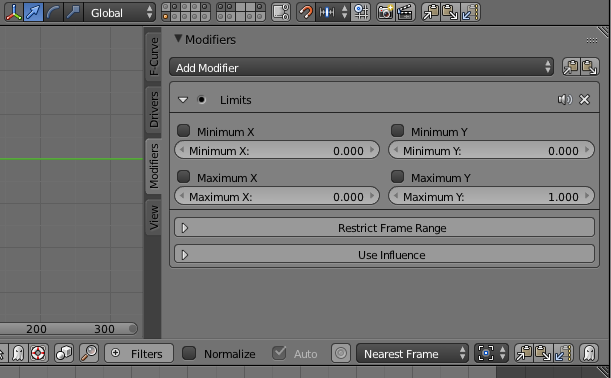
You rock dude! In the rig, I have a modifier. I need the strength to be at “1” when the bone is at “0” on the Y Local space and than, at “0” when the Y is at about “2cm”, completely off, if possible.
It is working, Thank you! Now I just need the modifier to be at 0 when the bone is at Y= 1.02646cm and to stay at 0 without going into the negatives, when the bone Y goes above 1.02646cm. After this the rig will be ready for production.