Hi, folks. I’ve made some inmprovements to a model I’ve been trying to make using the help follks provided in my previous thread, but I’m stuck with a wierd difference in the displays of the 3Dviewports and render output. I tried repositioning the textures on the object’s meshes because it was noted that, despite my efforts to prevent it from appearing to be so, the model looked as if it was carved from a single block of wood. I realized that the textures weren’t really positioned properly anyway, so I decided to make a propper go of trying to correct the texture’s position, now that I had the normals facing the correct directions. To help me ensure the the textures’ locations and rotations were correct, I added a some planes that were scaled up to 10 square B.U.and then positioned and rotated them to form a set of orthoganal projections of my wood material.
I applied the rotations and scales of the planes, but not the location so that when I looked at them, they displayed a 2D cross-sectional projection of of the material that I’m applying to any given mesh. This is helpful because, whilst the texture has infinite length along the Z axis, it is has a radius of just 1 B.U. in its local X,Y plane.
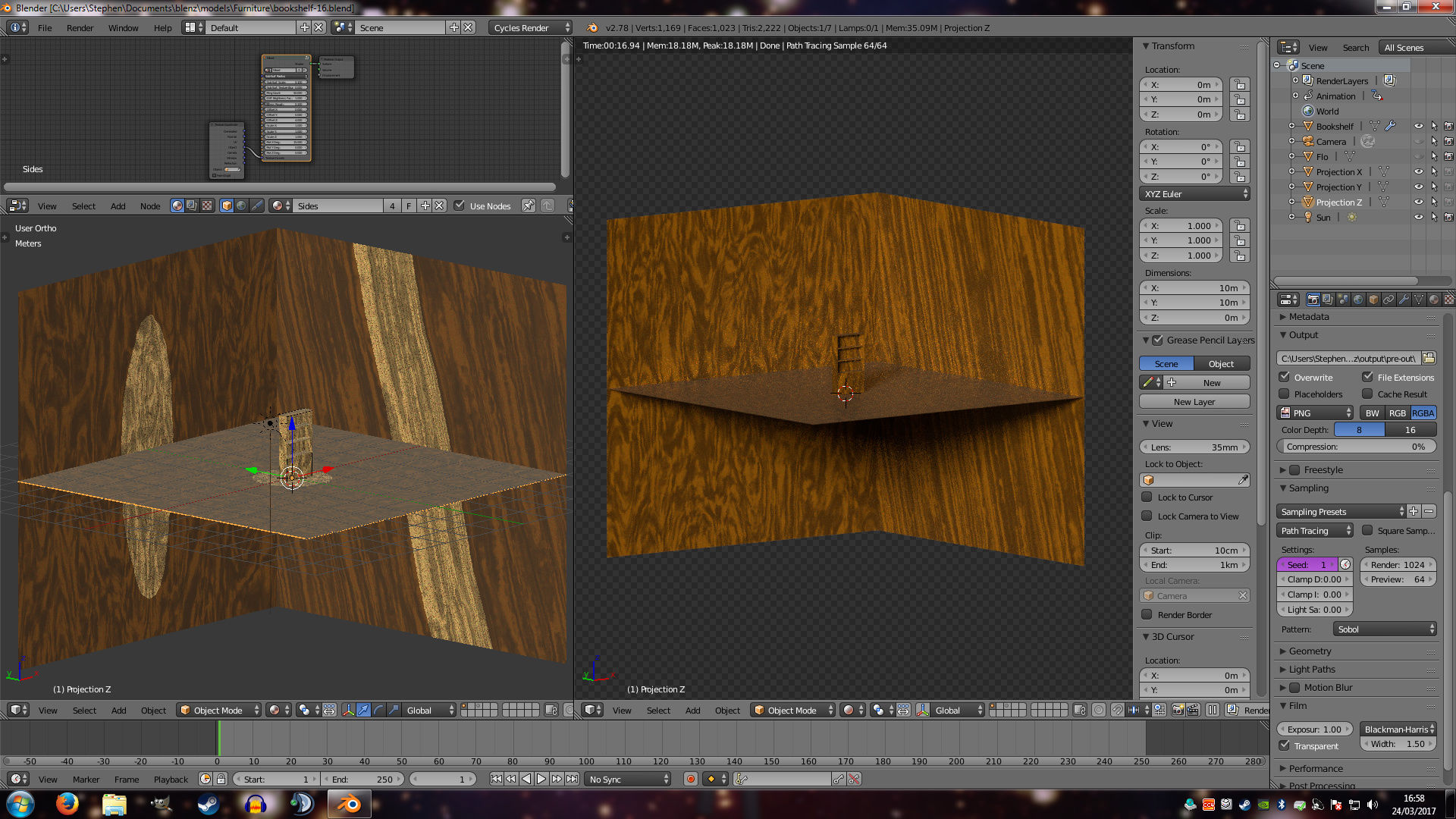
As far as I can see from the material 3D viewport view (left half of image), this worked as intended; however, when I view the exact same scene from the rendered viewport view (right half of the image), the texture seems to be in an entirely different location. Actually rendering the scene is, unsurprisingly, the same as the rendered 3D viewport view.
I take it this may be an extremely difficult problem to troubleshoot without me actually uploading my actual blend file, but I have no idea how. Can someone tell me how it do it for future reference, please?
Here’s the image that shows the difference in the types of 3D viewport views
I don’t think the UV layout matters, if it was even unwrapped. It uses object coords as input, and I don’t think that (assuming that is Skorupa’s setup) UVs are referenced within. Basically any object will be based on the object coordinate, but may want to zero out texture space if that somehow got set (in the data tab of the object).
If you want to rotate the input for a given pane say 90°, go into edit mode, select all, and rotate 90°. Go back into object mode and rotate the object -90°. If you want to offset it, adjust the 3D marker in 3D space and do Set Origin to 3D Cursor.
I’m still not clear on the semantics of UVs to be perfectly homest; I just have a vague notion of them being the image projected into the unfolded and flattened out skin of a mesh, nothing more detailed (or even correct) than that. So, as far as I know, my object does not use UVs. I’m trying to get the texture that’s prodedurally generated by the cycles material to be displayed with the desired location and rotation, and then once it’s right, that’s when I want to bake it into a UV image texture.
The problem I’m having is that I used the setup shown in the screenshot (minus the rendered 3D viewport) to give the cycles material the desired location offsets and rotations, but when I rendered it, it looked completely different. That’s what prompted me to compare what I was seeing in the material 3D viewport with the render preview 3D viewport and noticed that they were completely different.
In the image I posted as an example, the planes are used to gauge the location and rotation of the wood material that’s applied to the sides of the bookshelf. As you can see in the material 3D viewport (on the left) there are large areas that surround the desired mesh along all 3 axes. The panels in the rendered preview 3D viewport on the right, however, show that the cylinder of wood material is nowhere to be seen: just lots of extraneous guff from outside of the cylinder of material.
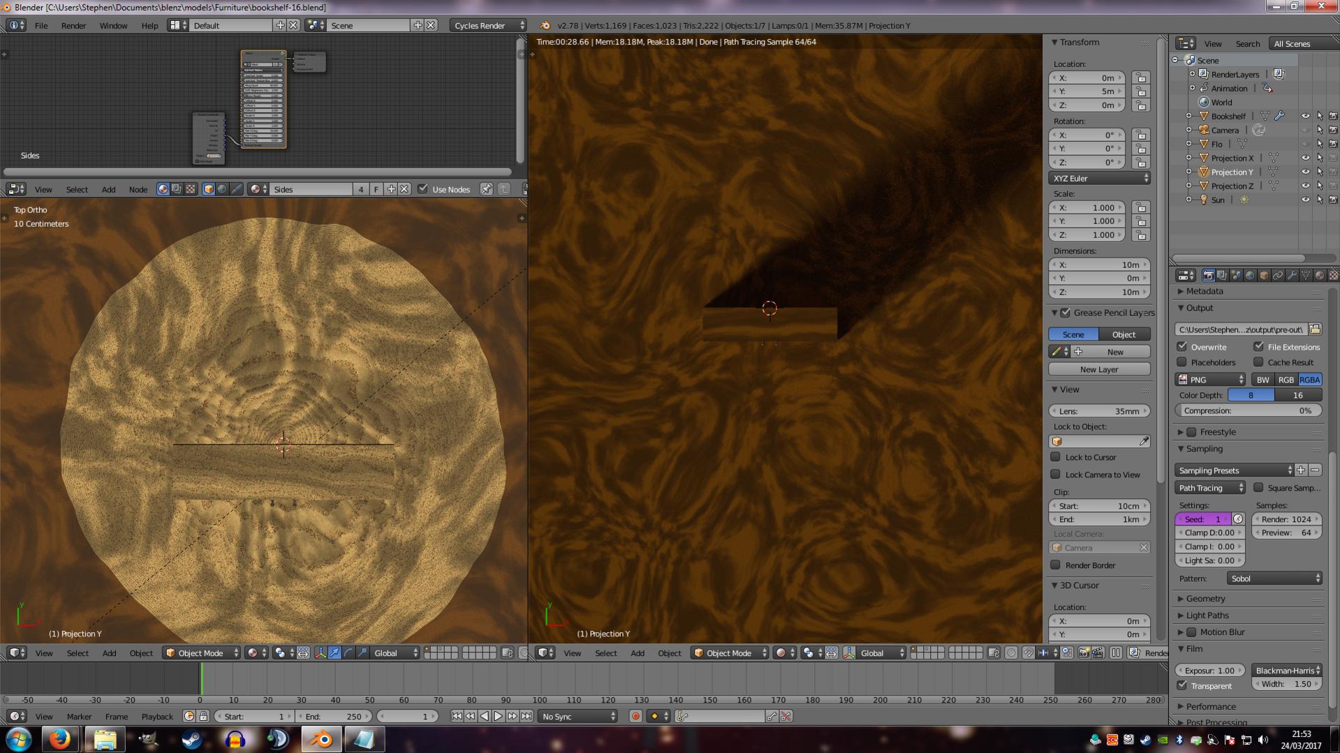
Here’s a top-down view of the same scene. Again on the left’s material view the circular wood pattern surrounded by the guff can be seen very easily, however on the right, it’s just all guff. The only explanation I can think of is that two different co-ordinate offsets/rotations must be being used, but I’m just an idiot with very little knowlege of how Blender does things, so I thought it’d be a good idea to ask the folks who know better.
If you’re going to bake, you need UVs setup. I made myself a bookshelf and applied a stretched noise texture to its main board directions using different orientation for each three setups. Unfortunately my viewport doesn’t respond at all to my texture setup, but also usually when it does kinda work it’s never very reliable. But rendering it I get what I expect.
With your shader where it actually represent a round lump of wood, you’d have to separate each board and set origin to center of geometry. With separate objects, you already have the basis to use the random input (if it doesn’t already internally, it might). Also, for safety, see if nulling out texture offset under the data tab (turn off auto texture space is turned off to edit). I’ve had cases in the past where I couldn’t get radial z tangent to originate from origin due to this having been set to something non zero by accident.
You can share the project at pasteall.org and provide a link if you can’t attach it here.
Just had a play around with the rotation about the Y axis and found a very definite miss-match between the views. The rotation about the Y axis of 15 degrees is the first image I posted, but when I set the Y rotation to 0, the projections match up like in the following image.
[ATTACH=CONFIG]477546[/ATTACH]
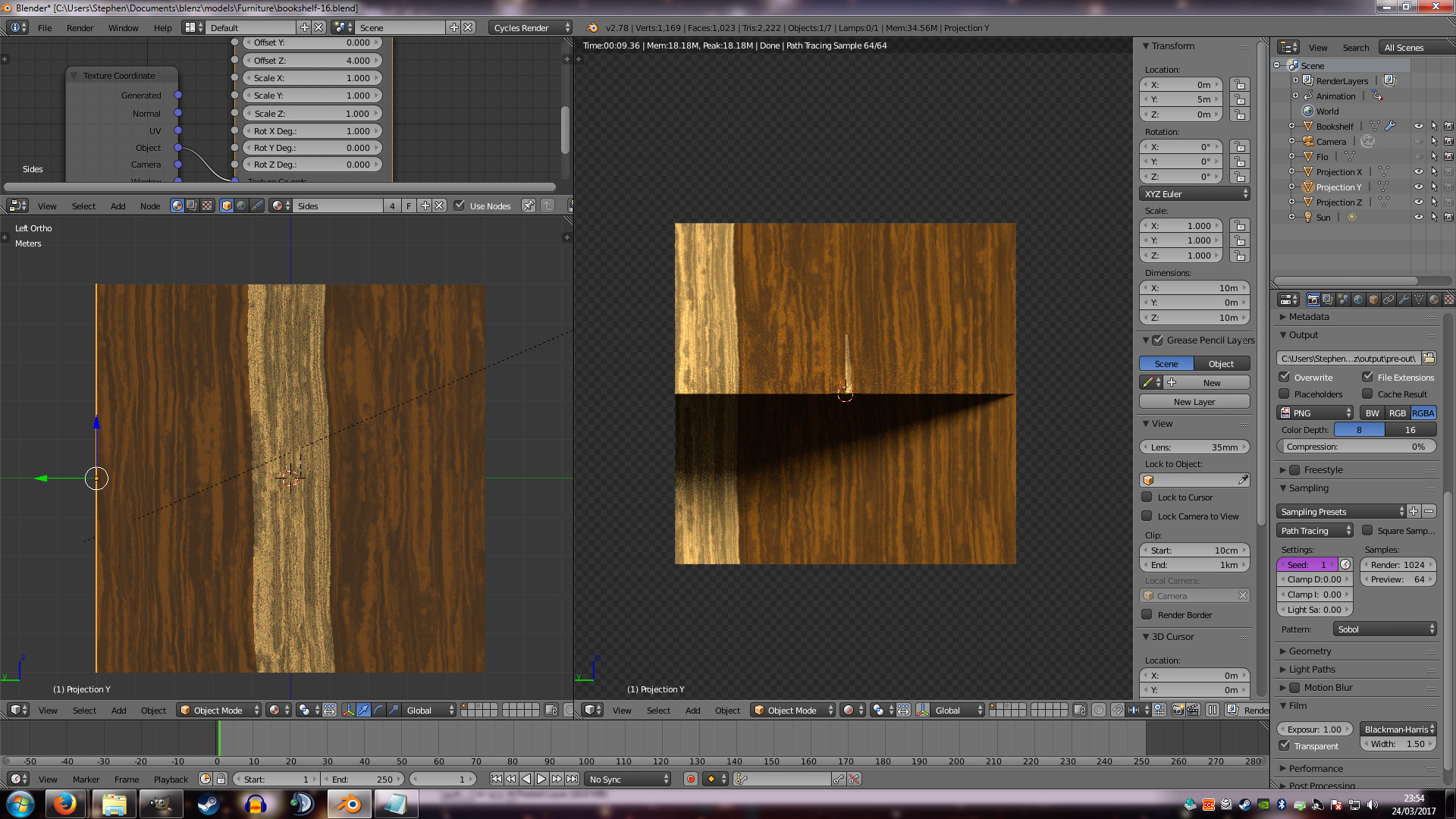
However when the rotation is set to 1 degree, a significant miss-match is exposed like in the following image.
[ATTACH=CONFIG]477548[/ATTACH]
The side orthogonal view shows the magnitude of the miss-match (at one degree) and leaves me totally baffled. The plane that shows the side projection just about catches some of the intended section of the material in the reder 3D view, but it is fully captured in the material view. The explanation that immediately sprang to mind was that the origin of the material’s Z axis must have been set to a negative number by the node group that randomizes the Z co-ord offset on a per-object basis, but I can’t imagine that’s the actual cause because, as far as I know, the randon seed is always a number between 0 and 1: It’s never a negative number. The other thing that leads me to think that it can’t be the offset is that an offset still wouldn’t explain the difference between the material and render viewports. The following image is of the right-orto image. Note that there is even a difference between the position of the material on the plane, and the material on the bookshelf despite their origins being postioned identically (with respect to the Z-Y plane, obviously). I’m just totally baffled as to why there is this difference.
Thanks for the advice Carl. I tried switching off Auto Texture Space, but nothing happened; it didn’t even prompt a re-render in the render 3D viewport. In your first paragraph, are you saying that the viewports are sometimes just unreliable and that I should just trust the preview viewport? If that’s the case and it’s a known issue, then I’m happy to just use the preview viewport work-around, I just assumed that the problem was with my understanding of Blender, rather than a bug with Blender itself. Is this a known issue, or have I just misinterpreted what you wrote? Thanks again for the help.
Thanks, JA12. I saw that button, but thought it was for attaching things like text files. Had a bit of bother merging the changes that weren’t sent back to the linked wood texture group node when I made them in the bookshelf blend file, but hopefully I managed it now. I’ve stripped out the wood textures on the other meshes’ materials so there is just one aspect of the problem to focus on; the fact that the two views show totally different positions of exactly the same texture material. I dialed back the X axis rotation of the material way down to 1 degree like in earlier posts, and then saved the blend with a good view of the difference.
Edit: Oh forgot to add a reminder. It’s the rotation about the texture’s X axis that’s causing the large miss-match. A rotation of 0 degrees gives the illusion of everything being fine, 1 degree and things go pretty wrong, and anything beyond that is just lost.
Hopefully, I packed it correctly and it’s properly attached. bookshelf-21.blend (675 KB)
Didn’t work, group not included. Was probably linked so you’d need to do a “make local all” or something. Regardless, I saw that the bookshelf object was still in there as a single object. Meaning that everything relating to object coordinates will have the same location and orientation. I made my own simple shelf thingie and used some version of Skorupa’s wood material on it. The steps I took:
Created rectangles where the boards would be.
Applied a solidify modifier. Do not do any merging or remove doubles.
Added a bevel modifier (non applied) for chamfered edges everywhere.
Added seams and UV unwrapped every single (now) cube in the mesh, prepping for later baking. Not optimal UV, was just a quick test.
Separated the cubes into individual objects, and aligned the Z axis with the trunk of the tree the boards would be cut from (see post 3).
Assigned and tweaked the wood material. Not too happy with the result, but again, just a quick test.
Made a 4k texture and baked diffuse color. Took a while so I had a powernap as well.
Rendered a test using the baked diffuse, using some factor for wood bump and reduced version for lacquer bump (less sophisticated than in the real wood, but just a quick test).
Result: It takes twice as long to render the real version compared to the baked version, using diffuse with two glossy and some bumps.
Is it worth all this work? I don’t think so, especially for a prop object. Sure, the real material looks pretty awesome wrt how it is 3D mapped and no seam issues, but having to use 4k texture for a bake is definitely not worth it memory wise for me. What I would actually do instead? Use a decent wood texture as a box map (or manually setup box mapping using different textures for endgrains) and use random input per board as a color to introduce texture offsets, rotation, and other random stuff. I might even blend it with a much simpler procedural wood texture. Much faster, and a lot less memory hungry, and nobody would care less about the look - only you would know you cheated. At the end (off course!) I went into the group and noticed a huge amount of noise generators, many with completely excessive detail settings - these can be turned down, probably even to 0 in some cases without a noticeable degradation in quality. Bookshelf3.blend (1.31 MB)
Yeah I was trying to keep it a single object too keep things sinple for me. I was just trying to apply different instances of the material to different meshes within the object to get it looking close to how I wanted it, then after that I was going to look at unwrapping it for baking. Anyway, I’ve made the material local and saved it again so here’s a, hopefully, working file. bookshelf-21.blend (1.09 MB)
Anyway, I’ll download tour file and have a peek now. Thanks again for the help.