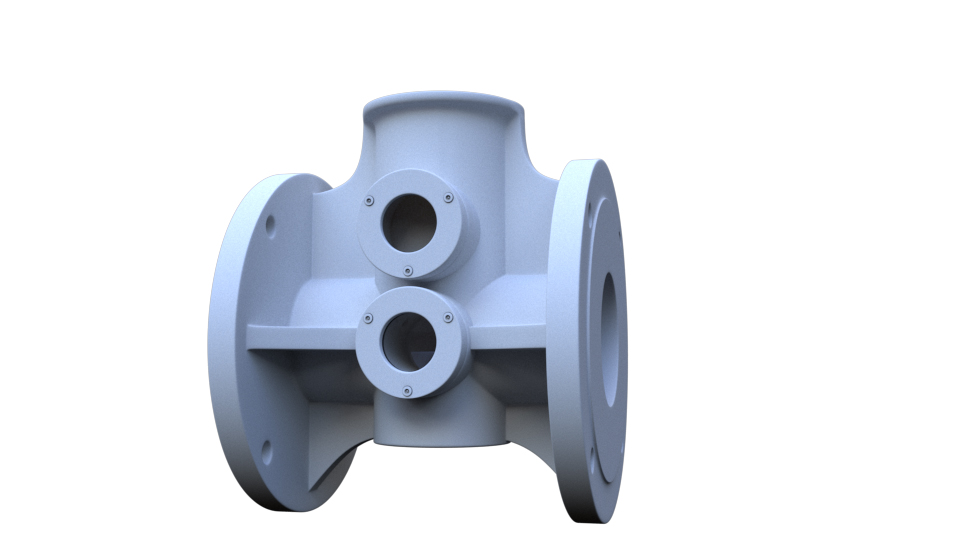
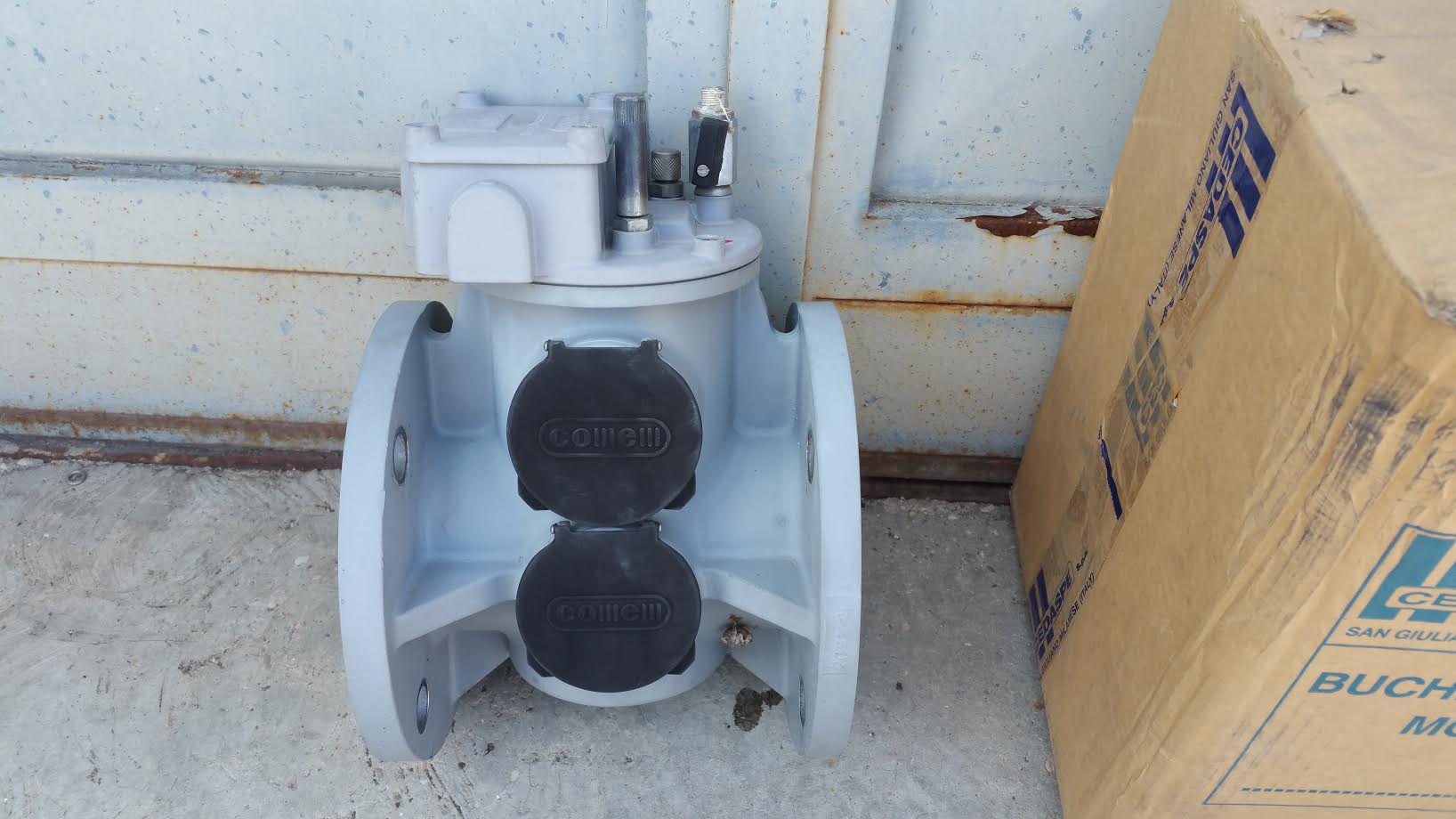
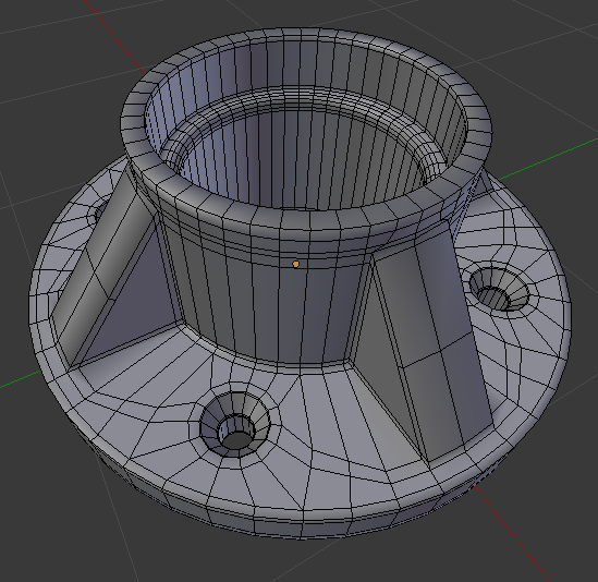
Hallo , can some one help me for modeling a shape like this?
Show us what you have so far and which parts you are having trouble with.
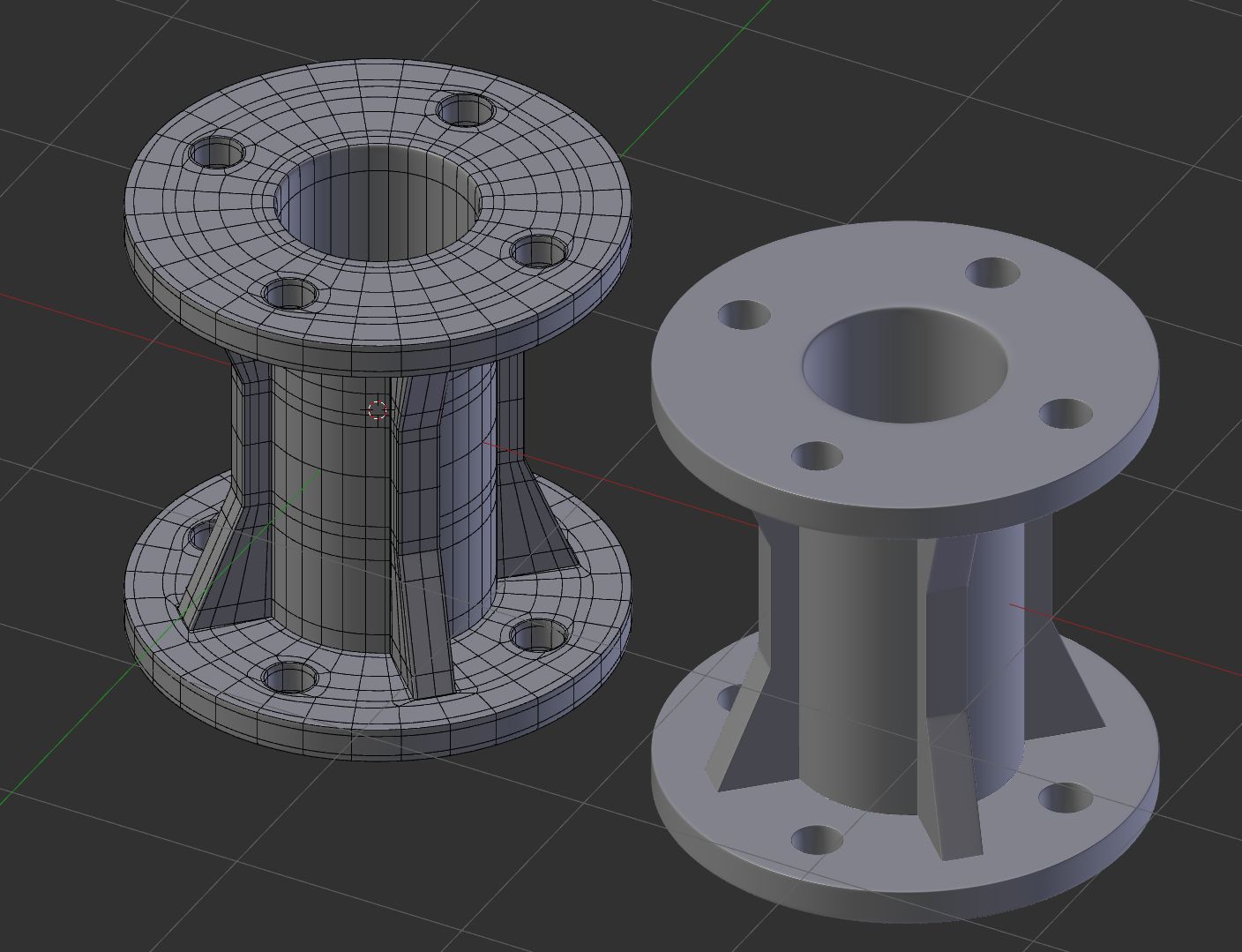
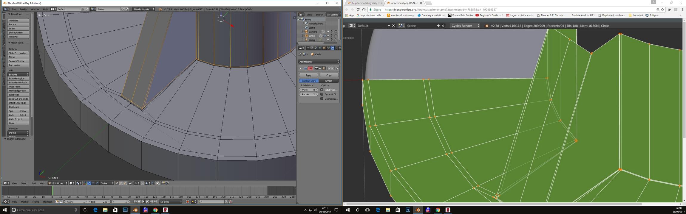
Thanks for the attention , i show my start it’s just an attemt because my firt problem is this
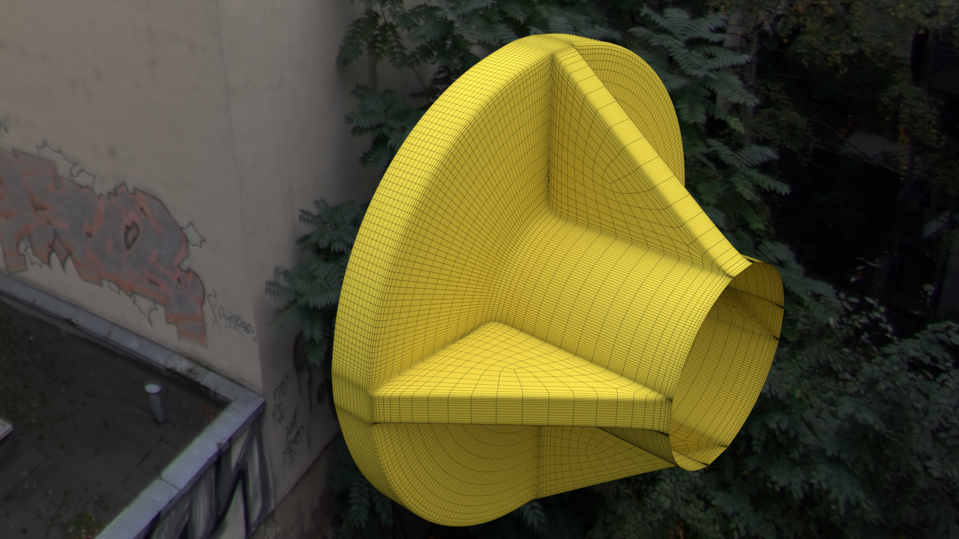
as you can see in this pics
the second problem it is to connect the flange to the body of the device without weird effect with susurfacemod.
Attachments
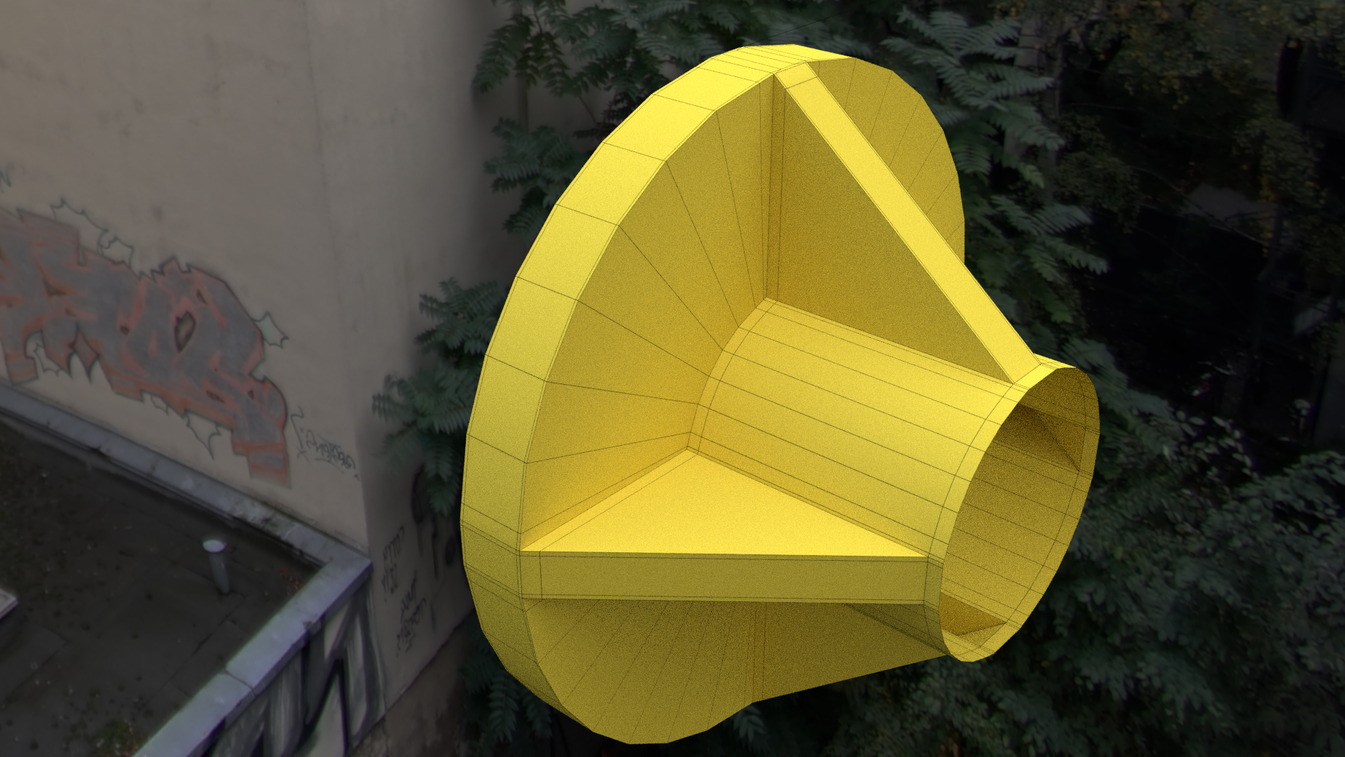
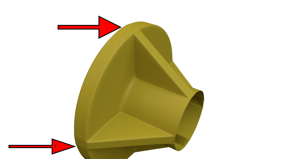
For the improper deform around the edge, look at the reference. The ribs don’t go clear out to the edge. You need an inner circular edge, and build the ribs out to that. The new circular edge will still deform a bit, but it won’t be noticeable.
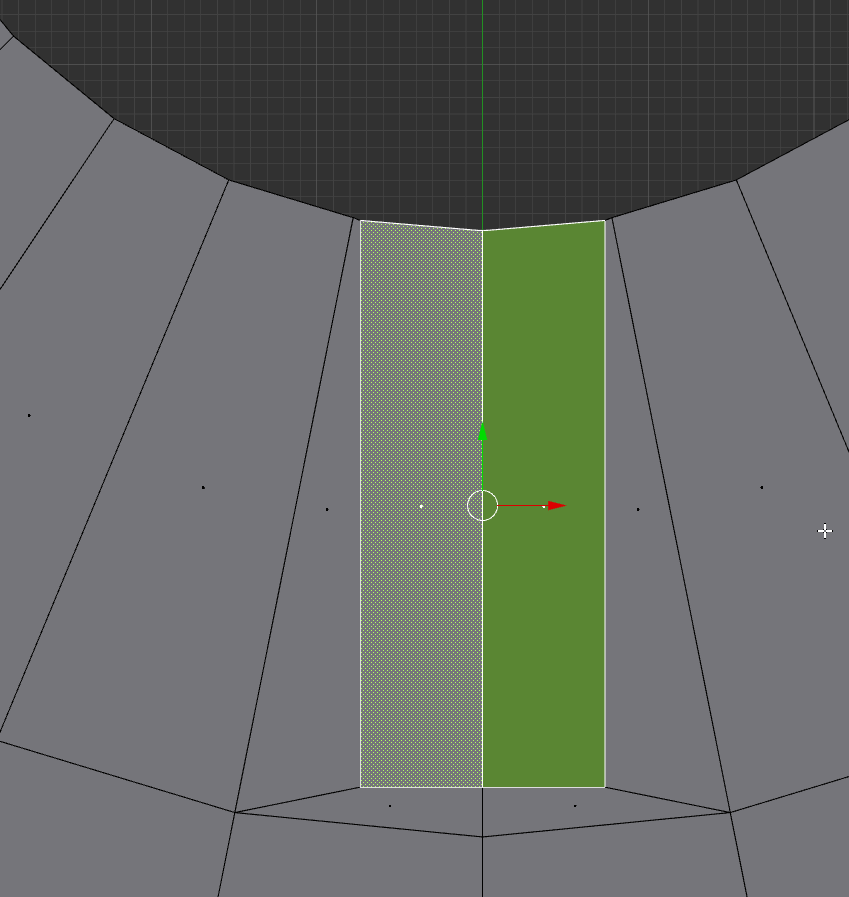
Since the support ribs don’t go to the edge (on the reference) this is a bit easier to fix. Select that one face loop, extrude by 0, then alt-S to extend those faces outwards. The loops will still have some flat areas on them. But among the default add-on set under prefs is Loop Tools. Enable it if you don’t already have it activated. Now you can select those outer edge rings on the flange rim and use the circle option from loop tools. (Under the edge menu.) That will fix the edge spacing to get rid of the flat spots.
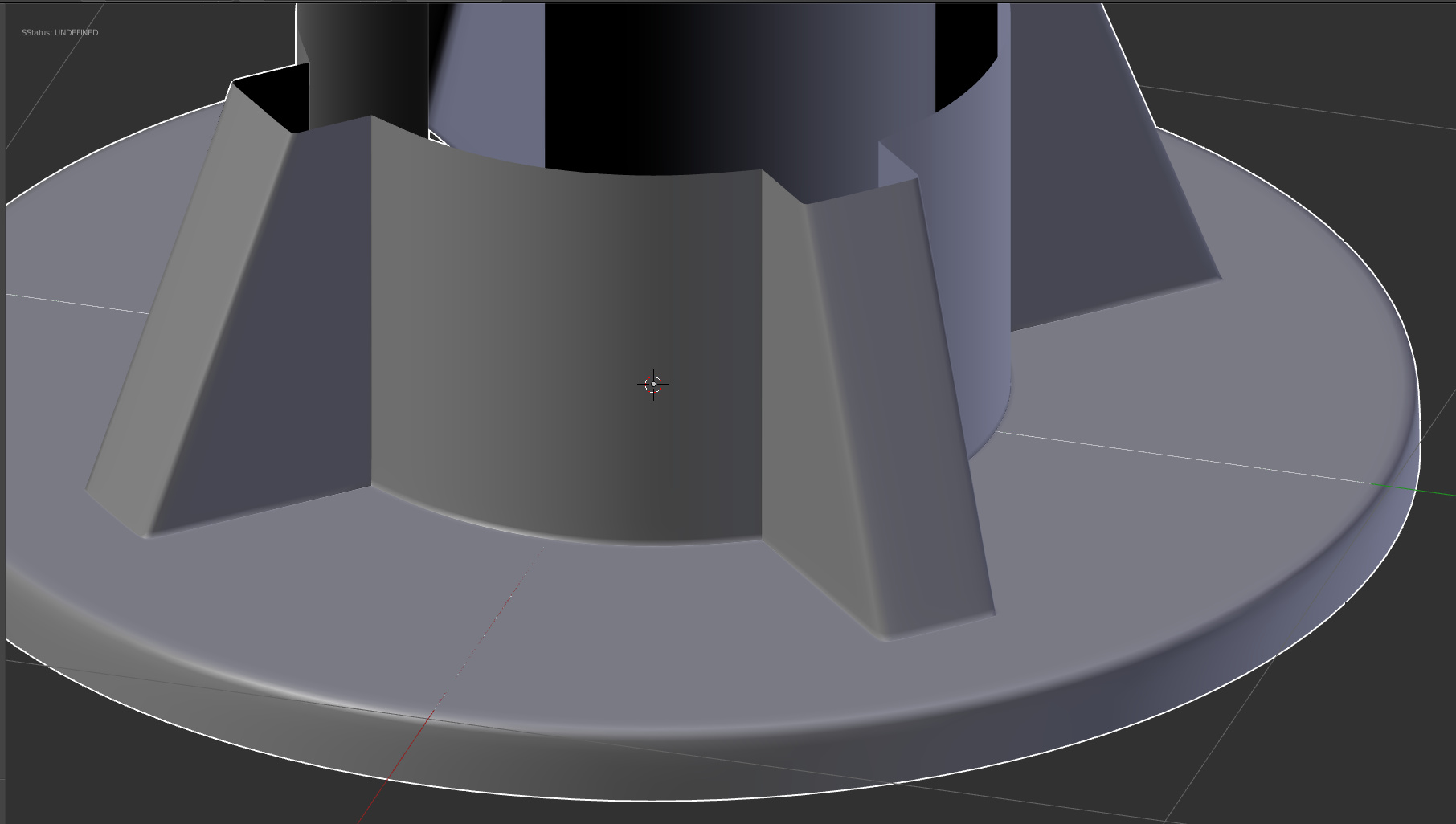
For eliminate completely the “flat” area, you will need work on the topology angle… merge the additional lines for end with the initial “curvature on the exterior”…
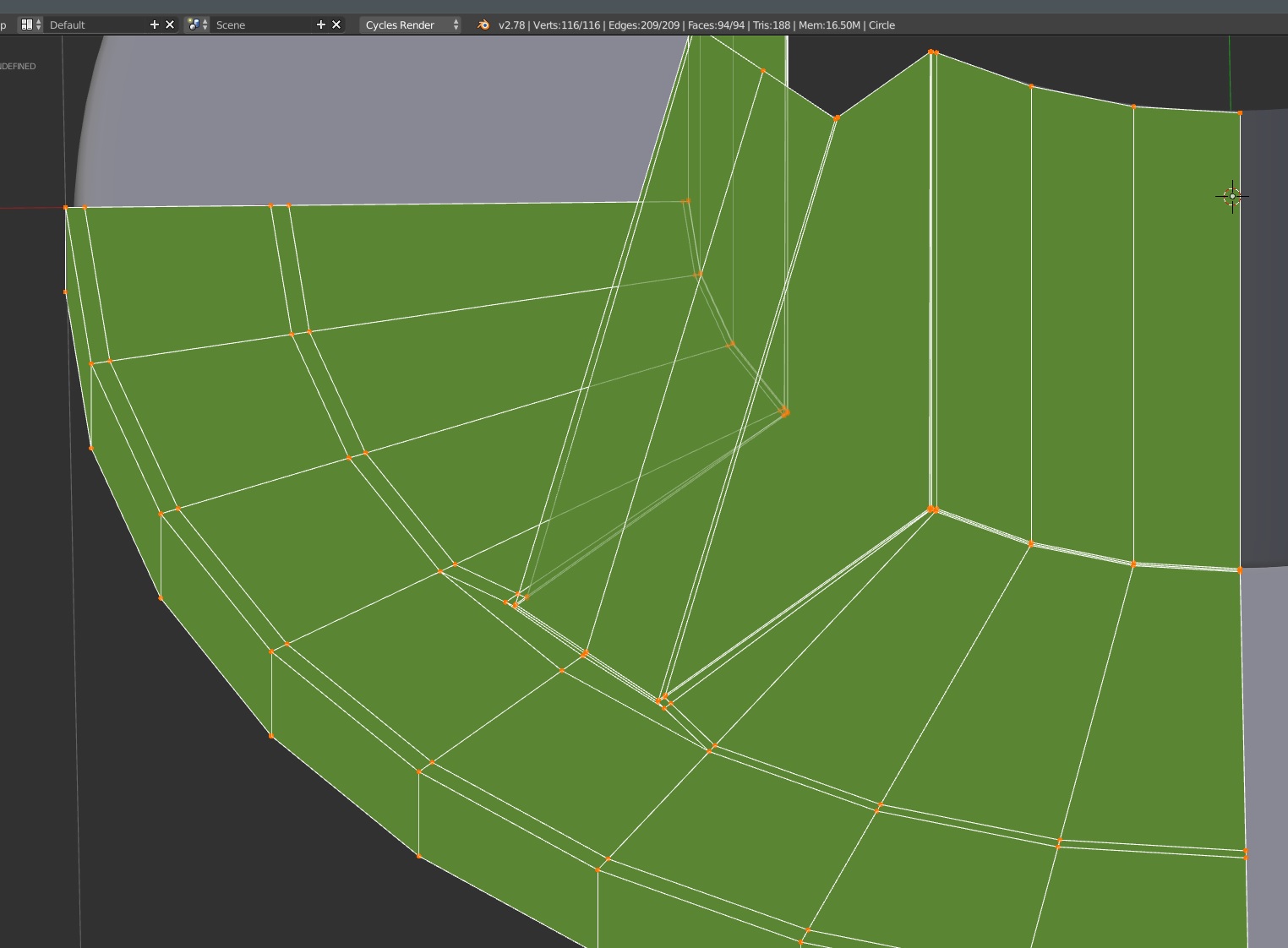
Again, theres different way of do it, i mot quite sure about my topology, but i wanted try with something else, using Inset faces.
Then extrude, create the “triangle zone”. and adding edges for supporting the crease lines. without touching the external curvature of the piece.
thank you anyone this is very helpful,i try immediatly.
The holes was made with boolean?
Was probably done manually. Boolean leaves you wish a messy mesh.
Manually… Its way faster than need to redo the topology after a bolean. It is the same technic that you can use on a square plane surface. http://topologyguides.com/
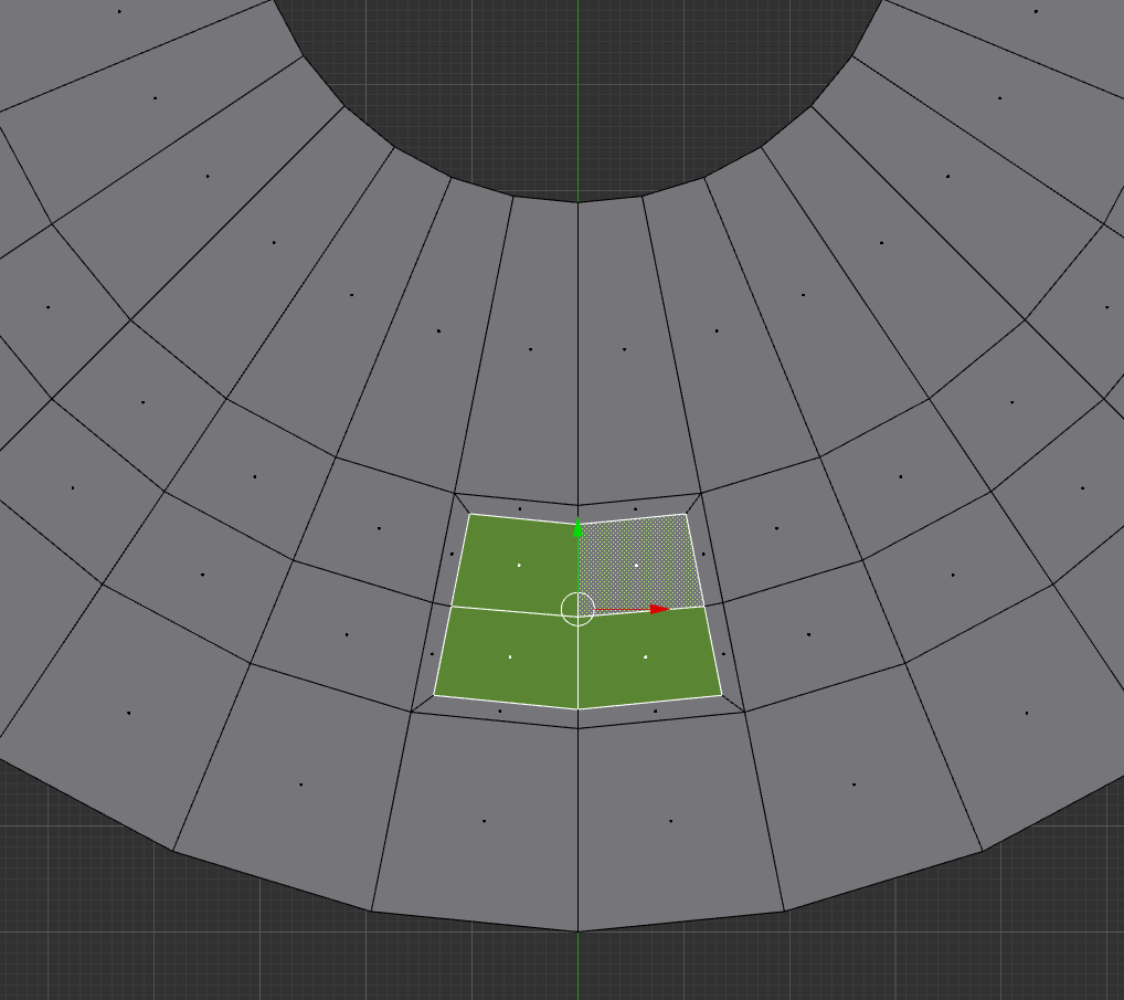
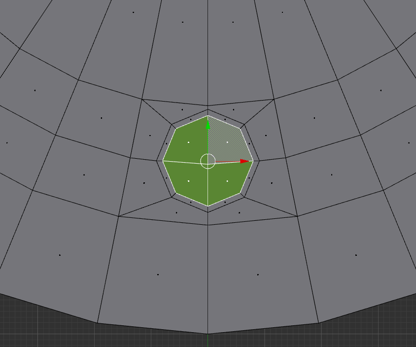
I select 4 quads, inset one time, then with looptools addon > circle and then inset one more time. ( will need to move some vertices depending the size of the circle you want or if the circle end bigger than the initial quads selected, not a big deal. )
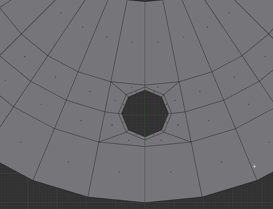
With subdivision surface modifier you end with perfect circular holes…
Yes it look good . Well there’s surely some different way of do it, but i was think this one is quite fast to do.
For sure it was vey istructive, i want try also the method of Pauljs75
But ther is a quickly way for connect the hole with the other face of the flange?
Topology could even been a bit optimized ( make it completely follow the interior part )…
For sure it was vey istructive, i want try also the method of Pauljs75
Yes, its good to try a lot of different technic, because cases wil allways been different, that will let the choice on how to solve each different one.
I have add a link on the first post, it is a topology guide with a lot of specific and more general cases.
Thks a lot hope to public quickly my primary substation. ciao!
My approach was basically on extending out that piece already there. But there are always plenty of good ways to do things in this program. Even playing around on my own (not really making much in particular), still similar edge-flows. And that’s where it counts. 
Admittedly loop tools is damn handy for this kind of stuff, regardless of which way you go.
not bad,is the same workflow of lane?