since there are many easy looking tutorials on how to make a 3D logo from SVG in Blender, I wanted to give it a try.
It turned out that even after watching hours of beginner videos on video2brain and youtube I’m not much further than managing to turn the imported file in a way I can at least see its front.
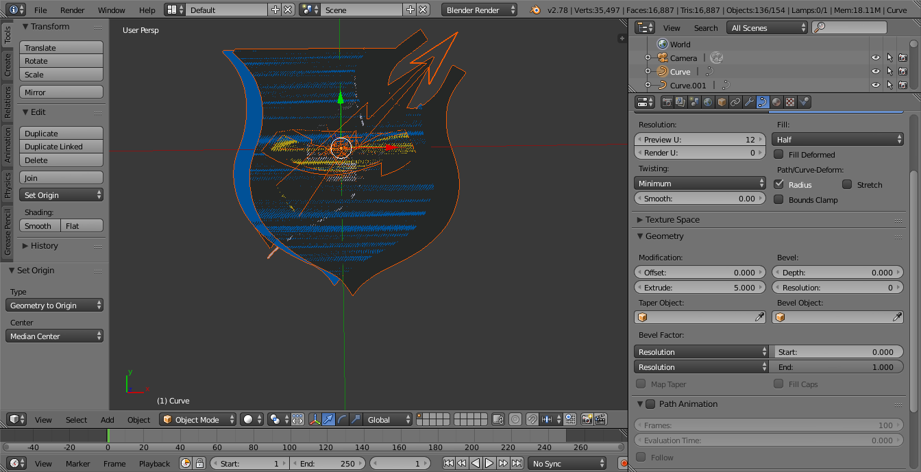
I managed to select the hole object with B+LMB (sometimes its missing a few paths, even I have selected everything with the square) but I can’t change “Extrude”. So I guess I have to set the Origin.
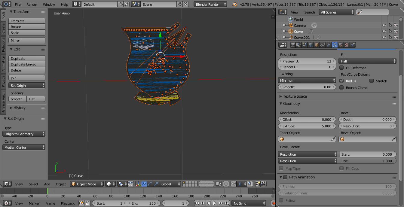
When I set Geometry to Origin, all paths are centered around the origin in the way that the object is divided into its paths.
You are showing a lot of objects, not one. Changing the values only affects the active object which is named “Curve” in the screenshots. Changing the same value on all selected can be done by alt+dragging, alt+clicking, ctrl+alt+scrolling a value/field/toggle/dropdown, or alternatively by changing the option and right click -> copy to selected.
You haven’t illustrated what the logo should look like, no example .blend to look at, don’t even know what the model is for, so really have to imagine the problem and the solution. I don’t like doing that. Tutorial linked in my signature shows a better way.
Is the step where you move the object to layer 2 and draw the lines necessary? And I can’t manage to extrude the hole embleme. I can’t follow how you are doing this. I always have only one path that is being extruded. Do you change the values with the mousewheel?
No, pointing to the relevant parts on the interface. The ones that get moved to layer two is to show that they don’t have any geometry in them, which is shown at the top header when isolated on their own scene layer, so they can be removed.
I’m alt+dragging the slider to change the values for multiple objects, as I told in post #2
I have “finished” the 3D emblem and some more questions.
First one is about how I have to make objects visible. I hope I can express myself in a way that one can understand, what my question is.
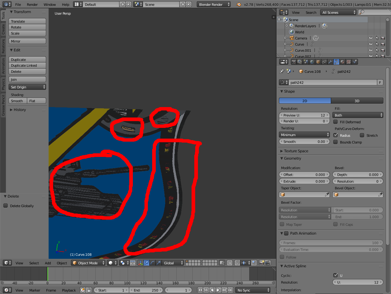
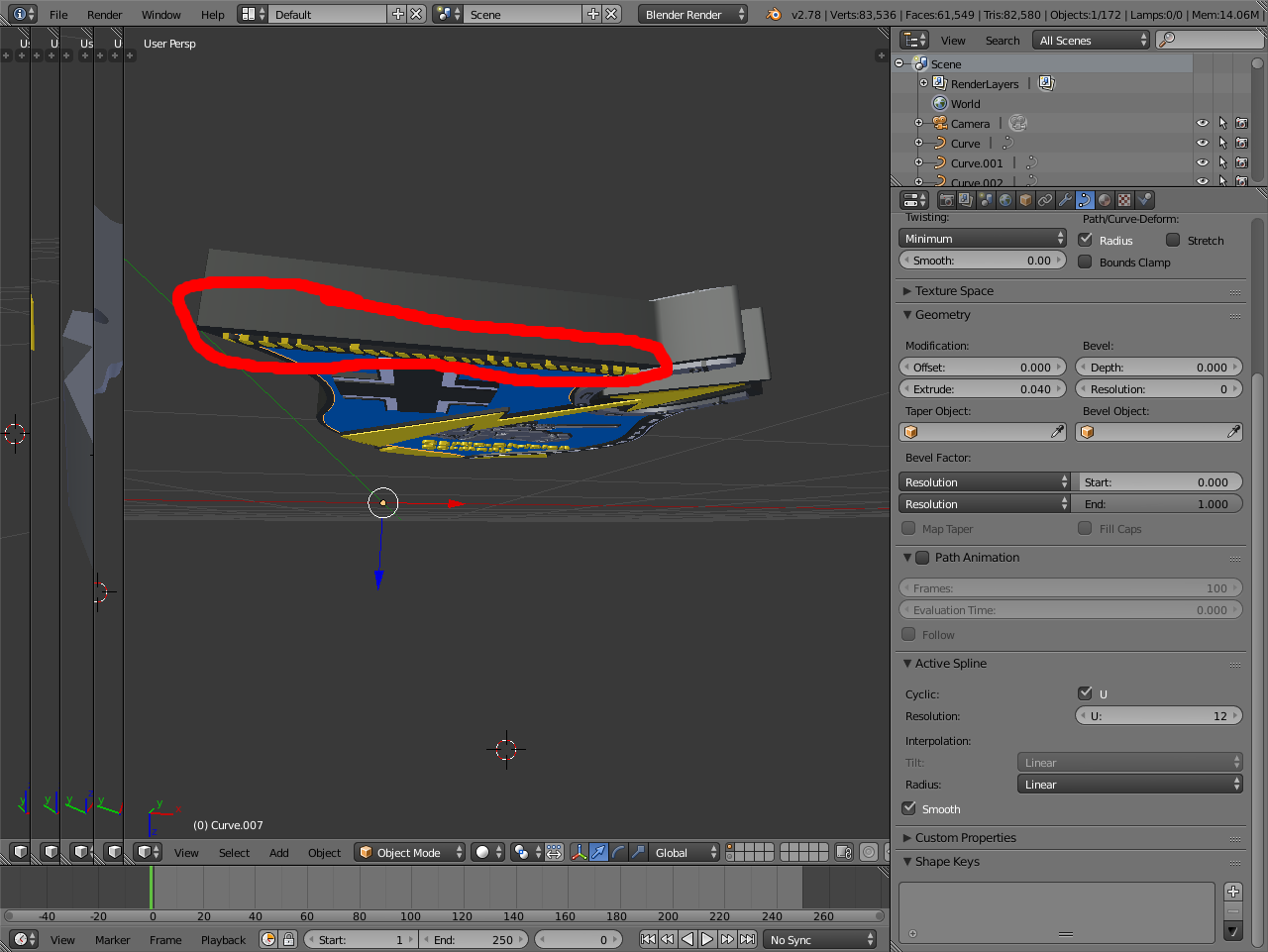
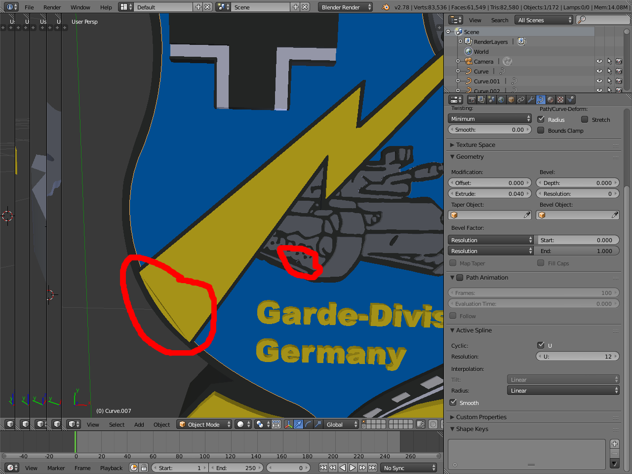
When I import the svg, some parts of the emblem look like they are striped. To make them visible I have either to pull them out of the emblem, or lower the surrounding object. Is there a principle on how this works and why is it this way, since everything is on one surface? I can’t figure it out.
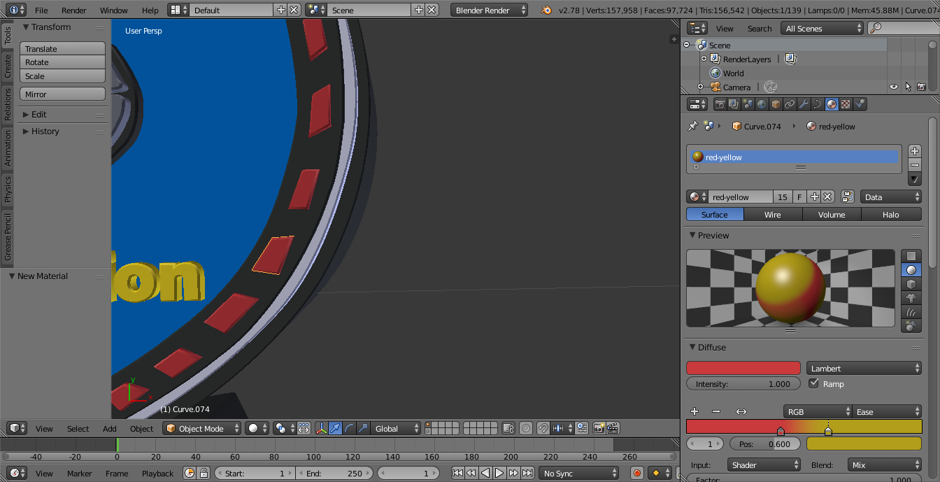
Second one is, why did I lose the red yellow color gradient on the right side?
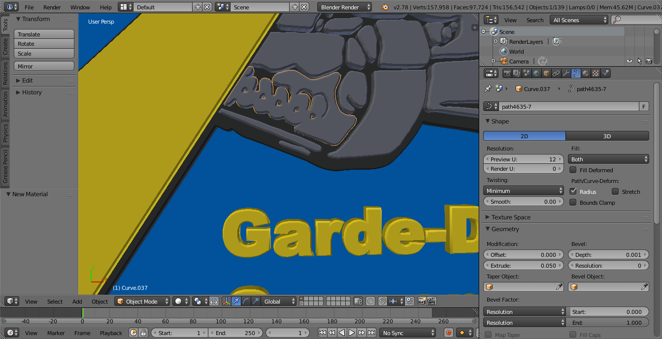
In the next screenshots there are defects/errors visible. Is it better to fix them within Blender, or in the original svg-file and start all over again?
As one can see in the screenshots I have many windows open. I can’t figure out how to close them and I didn’t find it in the manual, propably I’m looking for the wrong keyword.
Auto tracing in a vector drawing program is not likely to detect gradients, and those wouldn’t carry over to Blender even if they were defined as gradient in the .svg https://www.w3schools.com/graphics/svg_grad_linear.asp
Getting a path per color wouldn’t be feasible either, so would have to texture them. But, if thickness is all you want, could just get the outline and texture the whole thing
Depends where the error is. Distorted path: Blender or vector program, wrong placement/extrusion: Blender. There’s an error in the original image, some green line crossing over the yellow arrow.
I have worked over the emblem a couple of times now and the results are getting better bit by bit.
Blender-File
I have a problem with assigning gradient color.
I can see the gradient in the preview, but not on the objects. What am I doing wrong. I watched several tutorials on this, but can’t figure it out.
Curves set to use UV texture mapping and the gradient set as a procedural texture gives a better result. Not perfect though.
There is an alternate way, but there’s a problem with that too. Getting it mapped all the while keeping the objects as curves, rotating the objects without rotating the handles, and controlling the generated coordinates is quite advanced and would take a long explanation. Here’s the file anyway emblemnew3.blend (164 KB)
Enable compress from file -> save as dialog and upload here or pasteall.org instead of random site. Maybe a known cloud service if you know how to link directly to the file and not through the site, because they’re all crap.
Edit: recorded the screen
These might be easier to handle with unique material/texture and object coordinates perhaps, but as is the setup is problematic. The objects have applied rotation and the generated texture coordinate space only matches the global coordinates, and can’t rotate just the texture space. There’s also no way to rotate just the object origin (keeping the geometry in place) in default Blender, and haven’t found a good addon for it yet either.
As none of the steps to do those can be done on multiple objects at a time, used python to avoid repetitive tasks, for the most part.
I’m still dealing with this gradient issue. I did not understand everything you wrote in your last post. My problem is not the words, but the meaning.
Is this file suppost to show the gradient color? When I open it, it looks basicly like my file.
Do you mean this in generally on how to post/add blenderfiles?
I’m still trying to follow how you did this. This looks like advanced blender for me and I still don’t know much about coordinates and origins.
I also tried to turn the curves into mashes, just the objects I need the gradient for, and to use the texture paint mode. But this doesn’t seem to work either
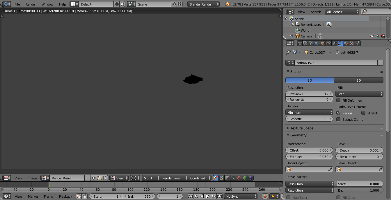
Shows up when rendered because of procedural texture
It is advanced. It shows what I did but not really meant to follow, could’ve used the ones in the file.
Yes.
There are multiple ways of making such logo, but each way requires various knowledge about polygonal modeling basics, the tools, materials & shading, textures, lighting and rendering.
Most importantly it requires decisions about what the logo should look like, what features it should have. Then it’s possible to suggest ways of making it. Still though, there is too much to explain in a forum post in detail.
This shows the process for texture painting, starting from the latest file. There are other ways to do this, cutting down the amount of painting and optimizing texture pixel area etc. but that would mean more explaining
If you try to do it the same way, the process is to:
set the object origins in the middle of geometry (tool shelf -> origin)
join the objects that are still curves (ctrl+J), and change their handle types to vector (edit mode, V)
convert the curves to mesh (object mode, alt+C), and join to the already existing piece that is already a mesh
cleanup: edit mode, remove doubles, delete all but the top faces
unwrap from view, pack UV islands (ctrl+P) without rotation and increasing the margin
change the brush bleed size and start painting
save the image after painting
the rest is done with a mirror modifier, extruding the faces to the mirror plane, deleting the extra faces inside, recalculating normals
and changing material settings to use the texture instead of color ramp
The simplest way probably is to define the outline with geometry and just texture that with the existing image. Not the same details as it’s using just the image for the colors but relatively simple
Hopefully those help because I’m done with this thread.


")
")