I looked at your file, but it’s really not obvious what you’re asking about.
Also, do you know you have two complete Blender windows open? The second one came up on my second monitor, so unless you have two monitors, it will be off-screen for you… which is why I bring it up. You may not know it’s there.
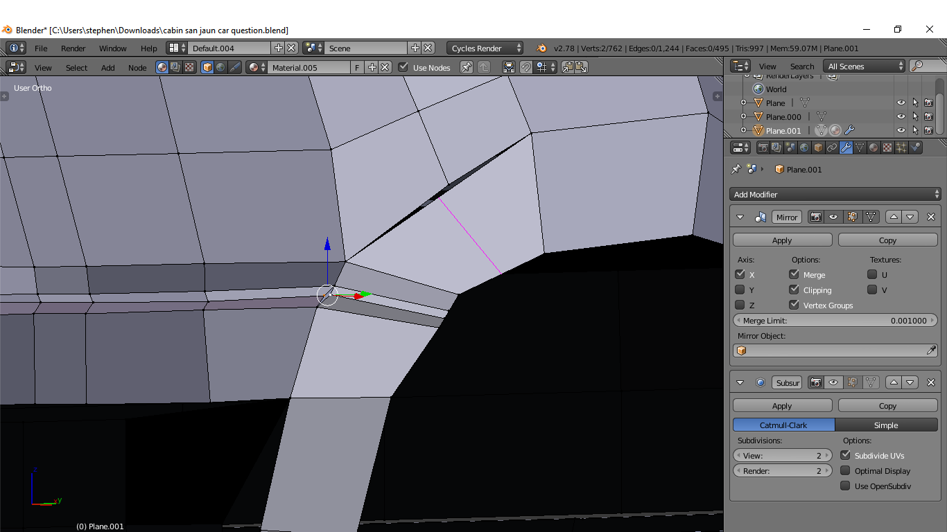
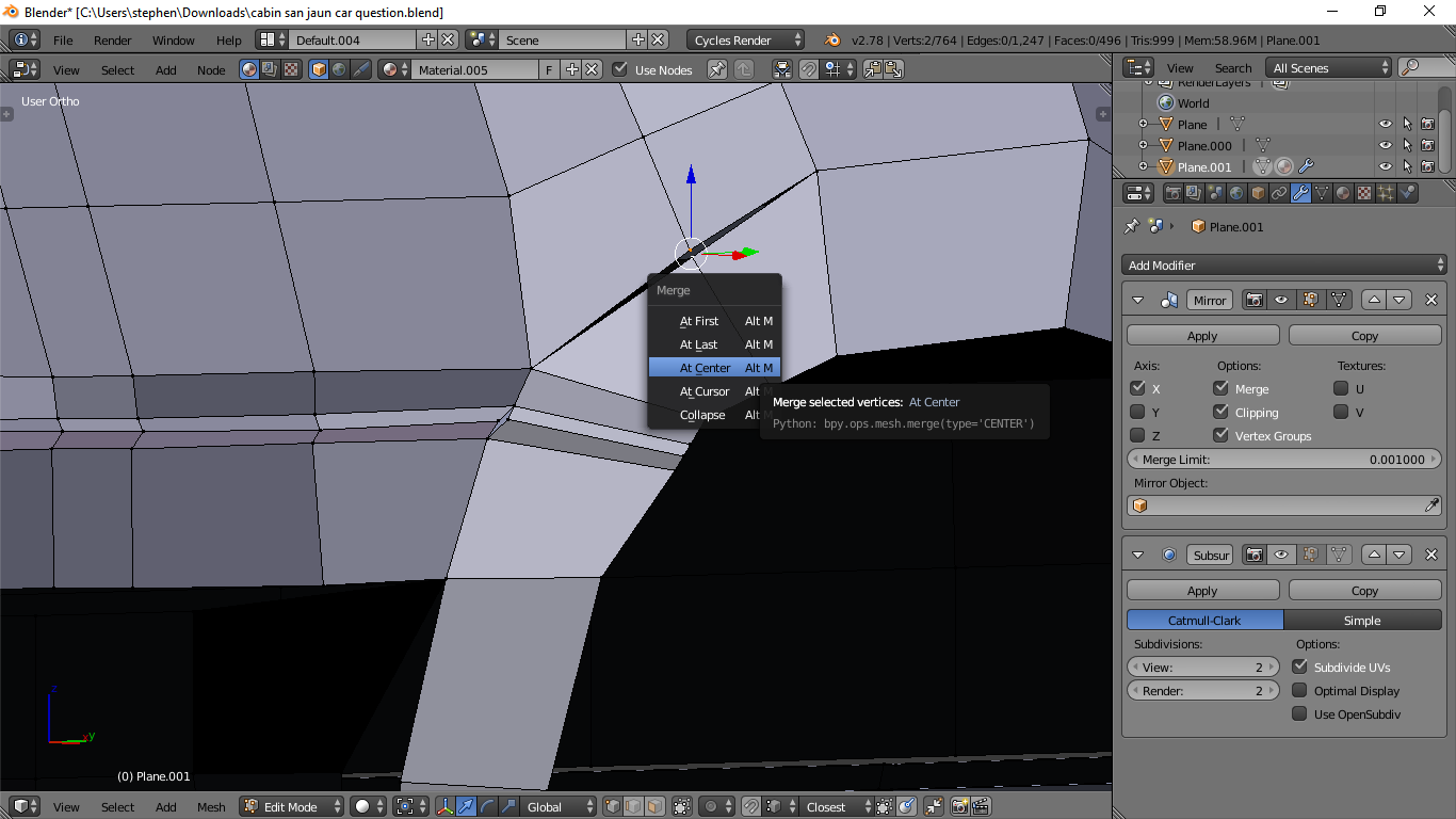
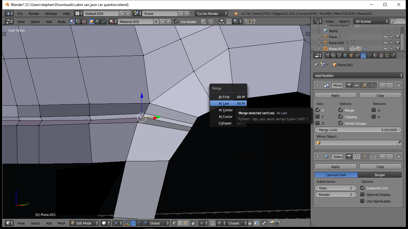
If I am following you correct here add a loop at the middle of the wheel well and then that separated section can be attached by selecting the one then the other vertex and pressing alt+m merge at center. Those will now be attached to the mesh. The other where the edge doesn’t match up you can do the same by selecting the middle vertex at the wheel well then selecting the other middle vertex at the edge of the wheel well and using alt+m again but selecting “at last” then those are matched up now and part of the mesh.
Hope that is what you were asking and rontarrant is correct that you have two instances of blender running, didn’t seem to cause any issues but once you start getting more detail and such involved it may cause some (depending on your machine)
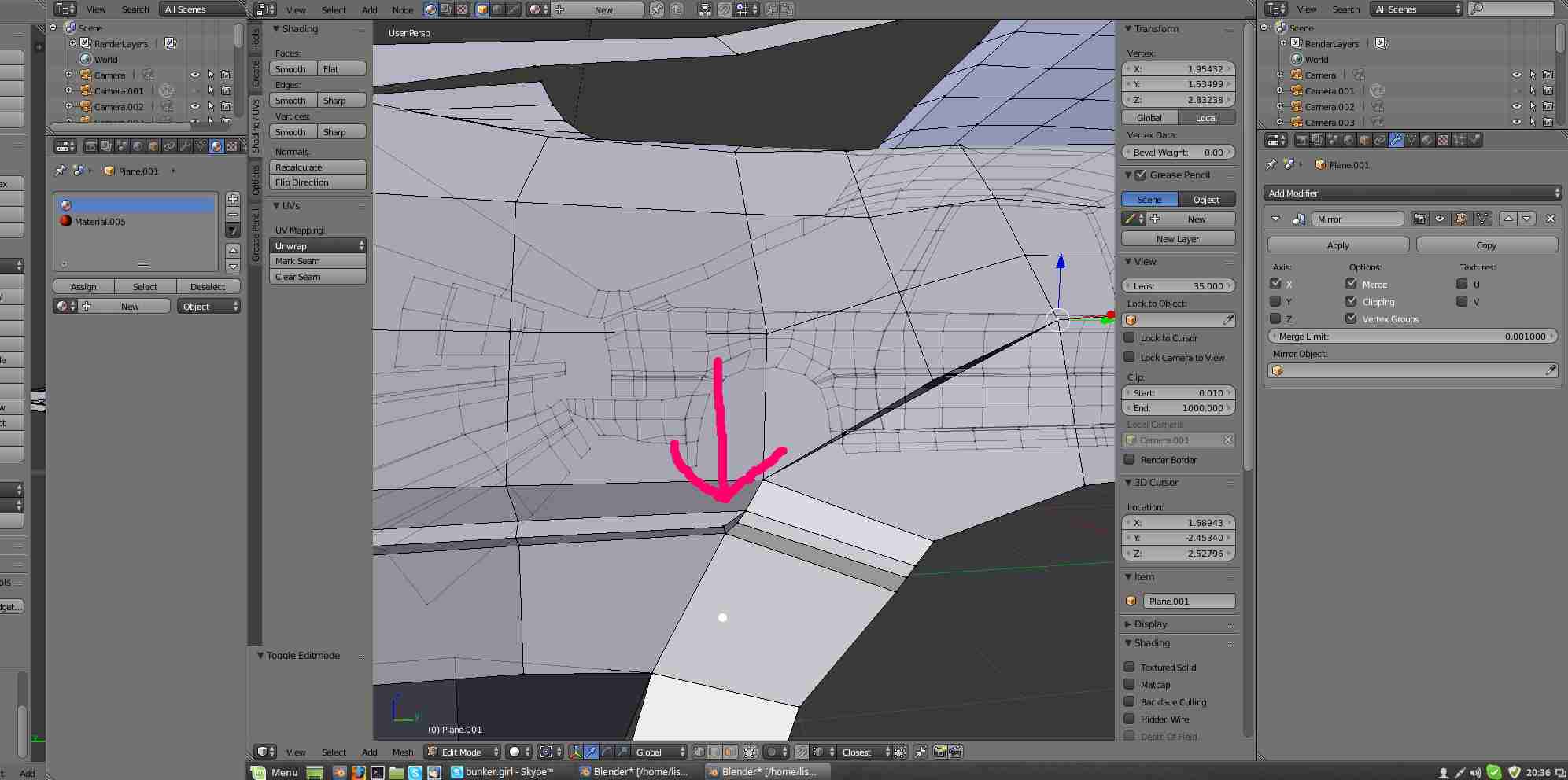
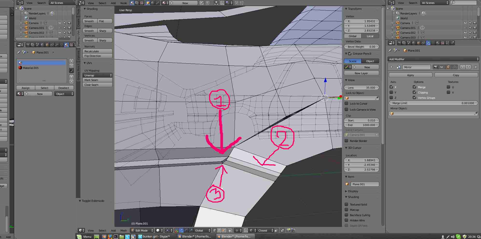
Thank u for your answers. I do have two screens going so thats not a problem. But it was not the merg i wanted to know about. If you look at the picture below then you see 1 is a raised edge made of three edges. 2 is a continue of the first edge but i don’t want it raised i want it flat. And three is a quad that i used hoping to get the raised and flat edge.
Connect them with 4-point face. If you want one to be cornered and one flat, of course.
To make it flat type s x 0 or s y 0 or s z 0 then rotate.
To make it cornered grab one edge or use shrink/fatten if edge is cornered already.
The trick for stuff like this? Start by modeling each of the major areas of the car as a single closed mesh. No worrying about the fine details. So the main shape of the body is one mesh, then the shape for the bumpers is poked right through that, ditto for major protrusions like how the wheel wells may extend out or another part like a hood scoop. And then maybe one or two levels of smoothing on those to develop the form, as the focus is only on volume and major contours. Yeah all those solid bits poking over each other looks awkward and perhaps a bit like crap. However that’s ok as all that will be the template. Now you create the actual final parts over that with magnet snapping to get all the separate parts and shapes, and alignment of vertices to the contours of the major forms in the template will be taken care of as you work out the desired edge flow. Then you can turn off the magnet and adjust things for the finer details. And if you need to bring something cleanly back down to a main panel, having that template gives you surfaces to smooth onto by snapping. Most of the time it works better than not.
Basically it’s the retopo-style workflow, but adapted to mechanical forms instead of the usual sculpts. Yes it’s more work at first, but it solves things like what you’re mentioning. (The wheel arch part would have a template mesh you’d just snap onto and reposition the verts to have it blend cleanly. You’re not manually tweaking a vertex on the X-axis 500 times to get it just right.)