Please be gentle, it’s my first post … even though I’ve been lurking on the forum for quite a while ! :yes:
I’m currently working on a headlight prototype, my vacuum formed shape can be seen in the photo below >>
I want to show my potential customers what the headlight cover will look like, But I also want to design the headlight mounting structure in Blender. Basically, my question is, can I design the headlight units independently then the plastic assembly and also the headlight cover in different files, and then combine them into one final image … like an ‘exploded’ view as it were ?
Many thanks for taking the time to read my ramblings .
Excellent, thanks Richard, I thought as much … it seems that there’s very little that Blender can’t do, it’s just the terminology I’m struggling with right now, not knowing what the actual procedure is called, makes things difficult to find. So, many thanks for that link.
I just took a look at your website, that CyberLeader helmet is a work of art ! and that ‘turntable’ thing is also what I would like my finished headlight to do, whereby rotating the finished headlight assembly, people could see all the way round the headlight assembly.
Armed with the knowledge that I can indeed add individual files to one another, I’d like to begin with something more simple than the twin headlights and the headlight mount as in the picture above. So I want to start on a mesh of the headlight covers as in the photo below >>
Could somebody point me in the right direction please … how would I begin to form that shape with the two cut-outs ? So, the term for what I’m doing is ‘Modelling a mesh’ is it ?
Richard - as you’re an Administrator of this site, will I have to fill in the ‘CAPTCHA’ thing every time ?
Well, looks like I’m on my own with this one ! a hundred views in one week and only one response !
Maybe I didn’t quite explain myself properly, or I haven’t posted in the correct section.
Should I be posting this sort of thing in the ‘Projects’ section of the forum ? What I need help with would be how would I go about designing a mesh of the white headlight cover above ? I’d be grateful for any help, suggestions … at the very least where I should begin, ideas perhaps ! Something that I could search for.
Loads of great Youtube tutorials but nothing specific to what I’m doing.
I can’t speculate on the lack of the responses. Without specific dimensions and without consuming too much time, here is a rough idea of one way to start.
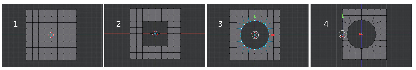
Remove the default cube and start with a plane. In edit mode, select all 4 vertices and subdivide 3 times (tool panel visible on left by typing ‘T’).
Border select (‘B’) the center 9 vertices. X to delete.
Border select the center rectangle and make it into a circle using mesh->Transform->To Sphere (shift-alt-S). You can drag to scale in or out but I recommend simply typing ‘1’ to scale it to a full circle.
Prepare to use the mirror modifier to create the other hole. I remove the left vertical row of vertices with a border select just to move the circles closer. To mirror we need the object origin on the left side; start by selecting a vertex on the left border. Use shift-S, Cursor to Selected, to move the cursor into position.
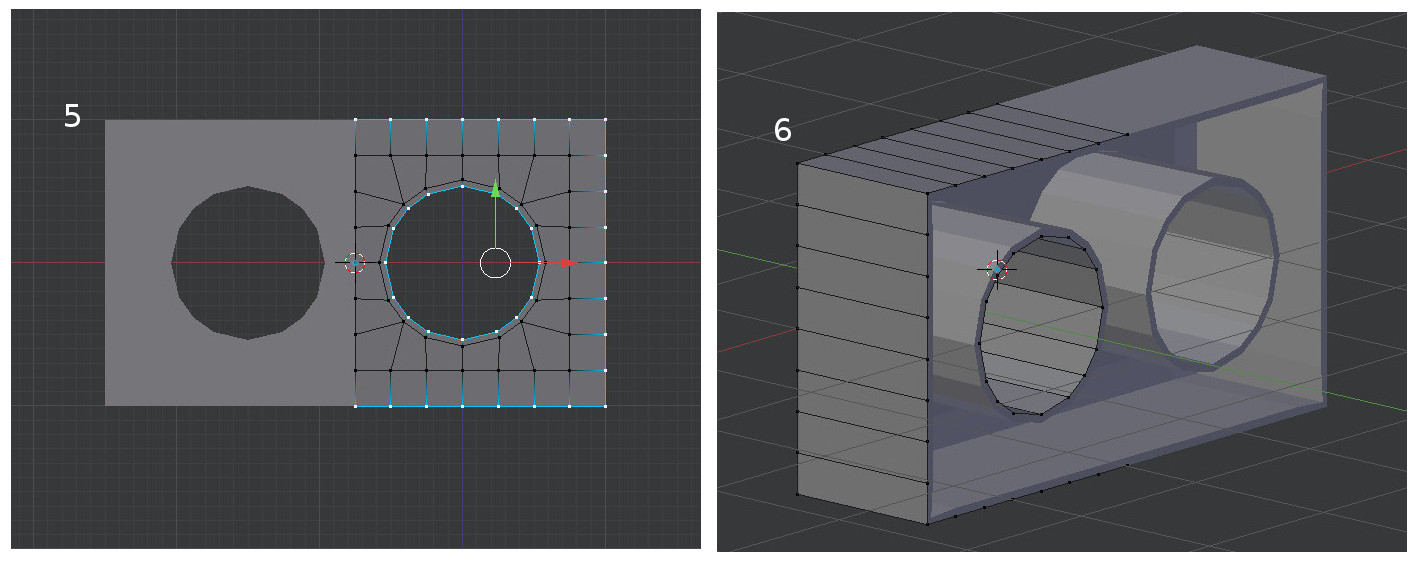
Tab to object mode, translate the object center to the cursor with object->transform->origin to 3d cursor. In properties panel, using the tools/wrench panel, add a mirror modifier. In the views above the x-axis runs left to right so I need to mirror on the x-axis. The image shows the mirror modifier in effect but not applied and we are back in edit mode. In preparation for extruding the depth I’ve selected the circle and border. (Sorry, when you weren’t looking I extruded a the circle slightly to aid in subsurfing later.)
After extruding back (in my case, the Z-axis) I’ve applied a solidify modifier with a thickness of .05.
Obviously, your project does not have square edges. Before extruding the cylinders and border, you could easily round the edges somewhat. Before sub-surfing you will also need to support some of the edges with edge loops. Also, your project is asymmetrical so you will need to apply the mirror modifier before those edits.
That’s exactly what I’m after, many many thanks for taking the time … apologies for having put you through that, I don’t know how much time you spent doing that, but your effort is to be applauded. I think the reason why I got very few responses was because my question ( and project ) at this time is still very basic, reading the posts on this forum shows that all the current members are well past my stage ! And people are probably thinking that I’m not trying hard enough !
I’ve spent literally days trying to cut holes in meshes, my concern was the ‘mirroring’ and ‘stitching’ of two meshes, negating the need of cutting two different holes in a rectangle ( which I also tried ! ), as I haven’t yet grasped the possibilities of those functions, but as you’ve kindly demonstrated it’s definitely possible.
As I’m still novice at this, I find that running a laptop next to my desktop PC very handy … I can follow the tutorials on Youtube, such as the one below, while I’m working on my PC >
While researching how the ‘mirror’ modifier works, the only tutorials I found were about mirroring a characters head or a car, models with totally symmetrical sides, but for what I was doing I couldn’t get it to work. Although very new at this, I’m beginning to think that before you begin a model ( mesh ) you have to plan in advance how you’re going to accomplish this, and my concern was … what if it’s not possible to combine the two halves together afterwards ! You could potentially lose days of hard work.
This really is fascinating stuff !
My main goal for this project is to demonstrate a product that I’m designing, with a view of adding an animated rotation of the headlight assembly, so people can see a 360° of the headlight concept.
So, many more questions will following I’m afraid guys … at least now I have a solid starting point thanks to g60.
I tried your way first g60, but I couldn’t get it to work unfortunately actually, I didn’t even follow it all the way through as I realised that cutting the holes in my mesh ( with a flat surface ), would deform the holes. So I had to ‘form’ my headlight cover first then cut the holes out.
I’d read about and seen on youtube the ‘Bolean’ method of cutting holes. So I constructed another mesh headlight cover then applied the ‘Bolean’ modifier … I am getting atrocious result though ! ( as in the screenshot ). I used cylinders as the ‘tubes’, but then I realised I couldn’t even modify them ! It wouldn’t allow me to resize the tubes down >>
As I realised this wasn’t really the correct method for what I was doing, as I need to cut out two holes in a curved surface, I decided to get back to g60’s method. Again, I had to model my headlight cover with all it curves … the issue I have now is, the squares aren’t quite ‘square’ ! Is there a way of aligning all the edge loops equally ? >>
The faces I have selected is where I need to cut the holes out, if I use g60’s method, will this mean that the holes won’t be perfectly round ?
I finally managed to find a way of cutting out the circles without getting too much distortion, but I’m stuck again !
I’ve highlighted what I’m stuck on … I need to enlarge the circle as I realise I’ve made it a little too small. It’s possible to extrude inward, but is it also possible to extrude outward ? … make the diameter larger as it were ? >
If you simply scale the circle larger — select circle and outer ring with ctrl-keypad+ and scale slightly (say s 1.2) — you will distort your overall shape. You might have some luck with a mesh smooth to get it back into shape — select all vertices, Mesh Tools / Smooth Vertex.
Another interesting option is to use the shrinkwrap modifier to create a 2nd object that can use the first object for shaping.
In the outliner give your object (“Cube”) a more precise name (“basic.shape”, e.g.)
View from the top (in your case keypad-1 to get to front ortho)
With basic.shape selected, duplicate the object with shift-d, enter without moving the new object.
Note that in the outliner, this duplicated object will be named “basic.shape.001”)
In edit mode, use the scale tool (s) to change the size of the hole. You may need to enlarge the surrounding vertices.
in object mode, use a shrinkwrap modifier and specify the target object as basic.shape. Apply the modifier and move basic.shape.002 aside for inspection.
As you might guess, the shrinkwrap method doesn’t work so well for reducing the size of the hole.
Considering you are in design mode, you might want to duplicate (shift-d) your basic shape without the holes. If it is in your way, move it to another layer. Duplicate that saved shape whenever you want to experiment.
The shrinkwrap thing is probably the best bet (along with an extra loop around the circular parts), then after you get that part right you can have it as a hollowed out form using solidify modifier. I’m going to guess that eventually this will be 3D printed, and then that print will be used for silicon molding an acrylic resin casting? (I’ve yet to see any direct 3D printing produce anything optical quality.) Then you combine that with LEDs and “mirror in a can” spray for reflectors…
I can picture that working successfully.
Will be neat to see Blender have a role in this, if it goes all the way through.
Many thanks guys for the suggestions, very much appreciated
I’ll be trying those tips tomorrow as it’s the middle of the night here in France … I’m about 9 hours ahead of you guys !
I continued regardless using the mesh you see above, as I just couldn’t work it out. I guess it’s not possible to ‘Extrude’ back on itself.
It doesn’t look too bad actually >>
You’re partly right Paul about the continued development of the headlights. No part of the assembly will be 3D printed however … The Blender work I’m currently learning will be for showing potential clients what my original concepts will look like. I create the moulds using RTV silicon rubber then cast a tooling resin in those moulds to make vacuum forming tooling plugs. Each part of the assembly is then vacuum formed using 3mm ABS, quite surprising just how solid plastics can be actually.
Here’s an example of the resin tooling plugs I made for the headlight mounting bracket at the top of the page >>
And the silicon rubber mould prior to casting the resin >>
Really enjoying learning Blender, amazing piece of software … really enjoying the research as well, even though most times I don’t understand the correct terminology. But I’m getting there :yes:
And with the help and support from the lovely people on this forum, I’m sure to get there quicker !