The normal pass is a compositor pass that allows you to bake normal maps from the camera.
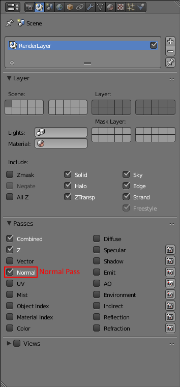
When you check that box, one extra output called “Normal” will appear in the compositor.
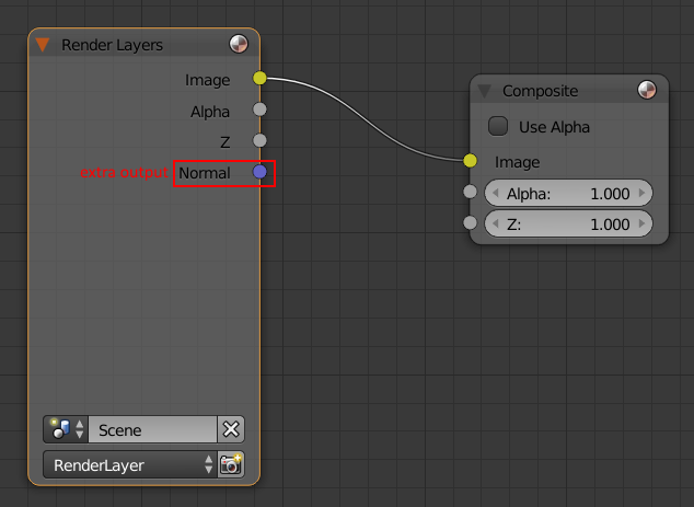
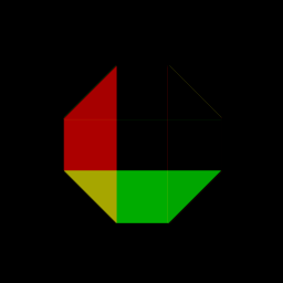
If you connect that output to the “Image” input at composite node, your rendered image will looks like this:
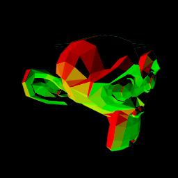
You can see the red, the green but where is the blue?
To answer this question, let’s make a normal map from this simpler object:
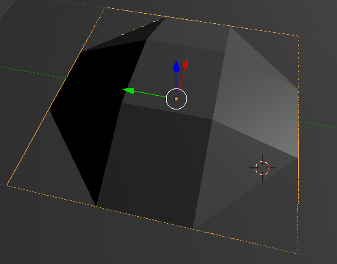
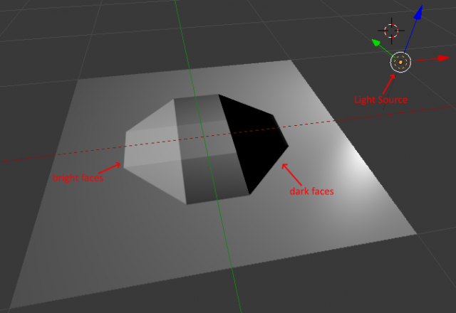
Here is a shoot from the top view:
In this image, it is easier to see the problem. The top and the right faces are not visible. But there is something there:
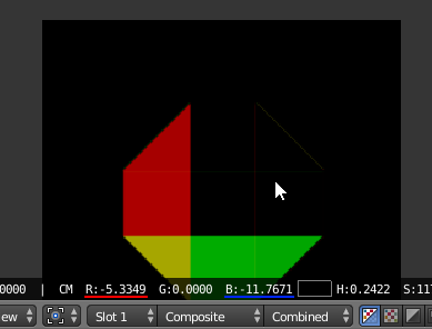
If you drag your mouse over the image in the UV/Image Editor, you will notice that the places where these faces should be have negative color values.
This happens because the Normal Pass stores the normal vector (the direction where the faces are facing to) into color values. The x is stored in the red; the y, in the green; and the z, in the blue. Thus, when the normal vector is pointing towards a direction where the x is negative, the red is also negative. But an image can’t store negative color values. Then, the correctly baked normal maps stores the negative directions between 0 and 0.5 in the color values and the positive ones between 0.5 and 1.0.
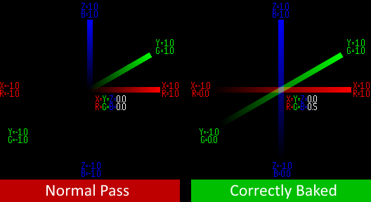
What we need to do is to push the negative directions to above zero and shrink their bounds so they can fit into the color value’s bounds.
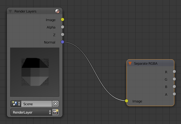
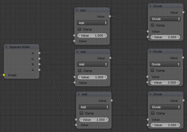
First we have to separate the colors so we can work on them individually. So, add a Separate RGBA node and connect the “Normal” output to it:
Now, for each color (except alpha), add two Math nodes. Set the first one to Add, link the color to any value and set the other value to 1.0. Set the second node to Divide, link the result of the Add node to the upper value and set the lower value to 2.0:
Let’s merge the color values together. add a Combine RGBA and link all the Divide nodes of each color to their respective input in the Combine RGBA node and link this node to the compositor output node.
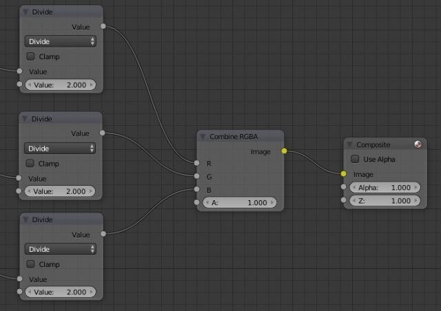
The result is now better. It looks more like a normal map:

But there still something wrong. If you use this “normal map” in a surface, you will notice that left side reflects to the right and the right, to the left.
For some reason, the red value is inverted. Let’s revert it by adding a Invert node to it.
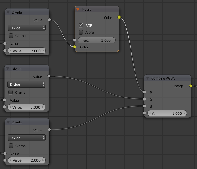
Now, your normal map is ready to use. Remember to save it in the best quality as possible. After all, for a normal map, color is everything.
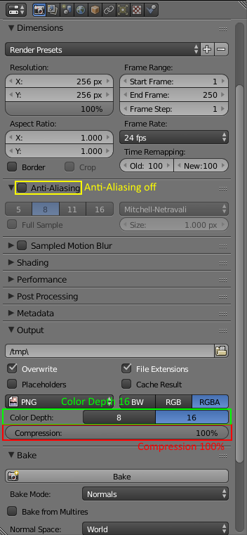
Set the anti-aliasing to off if you are working with a low resolution normal map and don’t want the bevel effect.