Full disclosure: It’s been a really, really long time since I worked in any 3D software, and even then it was only dabbling. I’m now trying to learn Blender and I feel like what I want to do is simple, but I’ve now spent an entire week on this and I haven’t made any headway.
Here’s what I want to do. I have an SVG design that I made in Illustrator that I want to import into Blender and make it 3D. But, unlike usual extrudes, I want the vertical edges of this one to start at the base of my shape and all slope upwards and inwards until they meet each other (or close, anyway). I assumed this would require an extrude on my SVG object, and then a bevel.
I can import my SVG. Sometimes, I can even extrude it (I’m new, remember). But the bevel has NEVER worked. It either does nothing (or I don’t even have access to the bevel option at all), or it applies an extra, outward-slanting bevel that makes the whole shape larger. That’s not what I want. I want to cut pieces away from my extrude, not add to it.
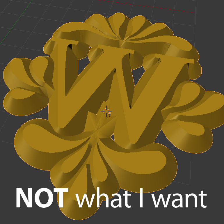
Here’s a photoshopped example of what I want to achieve (yes the W is mirror image - I’m trying to make a wax seal stamp). And also an example of the most progress I’ve made so far in Blender. Notice how the bevel adds to the shape, instead of cutting away.
I considered that maybe I was trying to learn on a shape that was too complex for me, so I made a separate file with a simple 6-vertex shape and did all my experimenting with that one too, with the same lack of results.
If anyone knows how to do this, I would appreciate advice so very, very much! Particularly with detailed steps - I am still getting used to the navigation and using my cheat-sheet of hotkeys heavily.
there is a option in curve geometry -offset, if you adjust than you can maintain width of base curve.If you use a profile curve for bevel i think u have to create it in top view(not front or left) and pivot point of profile will be placed on base curve.(you have to adjust pivot accordingly)
Remade is right. If you want to maintain the overall shape/size then you need to adjust the offset to a value equal (or opposite?) the bevel value. I use this method with text and I suppose your use here will be similar.
There are some signage applications that can do this relatively easily, but there are some compromises, and the file may not be exportable to another application.
An alternative method that is commonly used is a displacement/heightmap.
This requires a very heavy model since the surface must be subdivided many times to provide the level of detail needed. The displacement map is created by using a blend (in a vector drawing application) between the top shape and an offset bottom/base shape, or insetting the bottom/base shape to create the top. Even with a high # of blend steps, this can result in a stair step effect in the displacement created from rasterizing the blend. One solution is to convert to 16bit greyscale and use gaussian blur … this gives 65536 steps instead of the 256 limit in an 8bit image.
Its possible to use levels and curves or other filters to modify the bitmap to produce a different effect. The advantage to using the signage applications is that they usually have tools to quickly modify the profile or angle of the side.