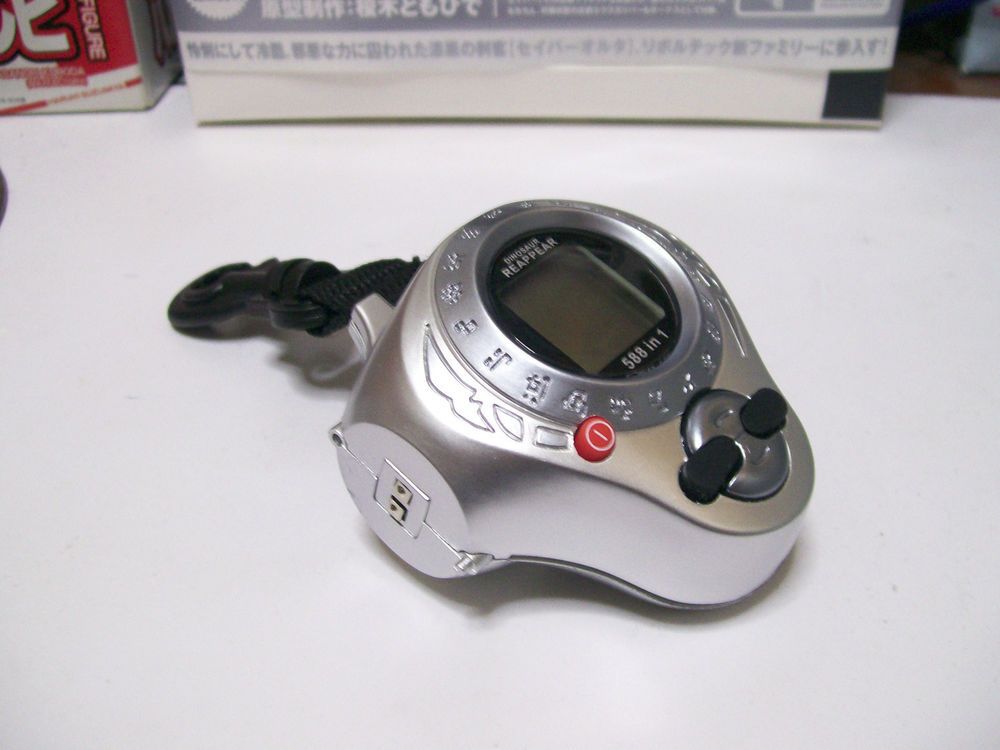
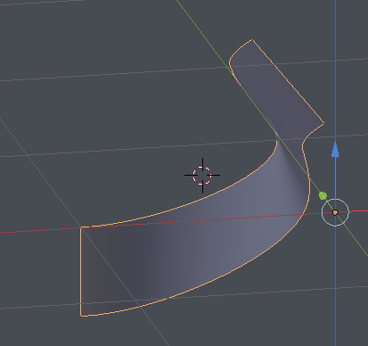
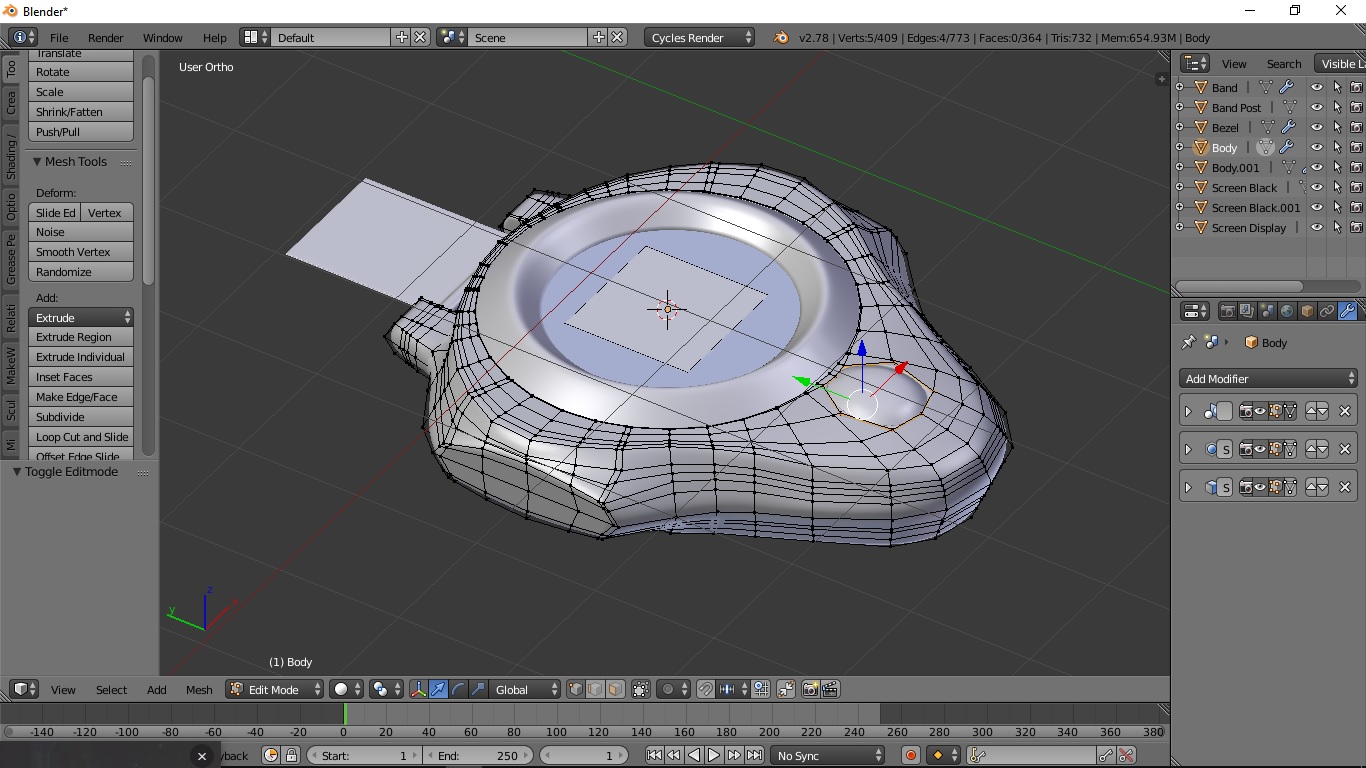
I am trying to model this device and I am stuck on this particular surface. I have modelled the face, the round side and the middle edge of curved surface, but I can’t figure out how to model this one part. To me it looks like blending between multiple curves, but I can’t wrap my head around it.
Just for practice I gave a shot modeling this as well and I went much the same process as I would when doing car modeling. The main thing I can see looking at your blend file is almost all your pieces were tri’s. Quads will allow for more manipulation and edge flow control as JA12 mentioned so you can get hard or soft edges where you need them by adding in a loop or bevel.
I quickly modeled the basic shape to show how I would generally start a model like this. I didn’t model directly to your reference so proportions are off and there are lots of details and some basic forms still missing, but hopefully seeing the initial topology helps. There are other images online that show other angles of this object as well. It’s always helpful to find as much reference as you can from different angles to help figure out what’s going on with the forms.
Thanks all. I ended up using JA12’s method realising that, once subdivision is applied, the sharp edges smooth into the required shape.
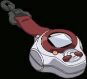
FlyingBanana, it’s called a “Digivice D-Power” (or “Digivice D-Ark” in Japan).
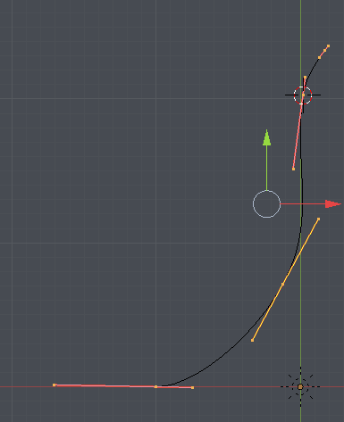
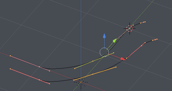
The reason I have mostly tris is that it’s what Beauty Fill gave me. The way I started modelling it was to take reference images and trace the features I could with curves and 2D outline meshes. The next intended step is to fill in the pieces, and make the necessary cuts, etc. which is where I got stuck. Your mesh looks very nice and I wish I could get mine that neat. How did you do the top surface?
I started with just a simple circle without a face. Set it up to the size of the blue bezel piece then extruded/scaled it out to the shape of the top then extruded again and left it in it’s position (I kind of guessed at the halfway depth position) for that second extrusion I pulled down on the z axis to the halfway point. Then I duplicated the top flat section and placed it below the second Z axis extrusion about at the depth required. I now filled in the faces from the bottom (duplicated verts) with the bottom section of the halfway point. Then I was able to add in loops as needed to shape the top section and the sides. Now for the flat side oval sections I selected the inside faces and deleted them, selected the edge of the hole and hit space then selected “to sphere” creating the oval shape then scaled it as needed and filled. I did also use a mirror modifier and a subdivision modifier along with a solidify as well during the creation. I can share the .blend if you want it. As I said I was just doing this to see if I could model it as well. I am still learning myself so I tend to take the long way around things but getting better slowly.
I’ve Re-jigged based on everyone’s suggestions and uploaded the updated version. I’m not using a mirror modifier because the power button is only on the left-hand side, otherwise I would be using it.
I’ve never seen the “To sphere” transform. I’ll need to look into that one.
Use the compress option in file -> save as dialog. Takes the file size down for up/download.
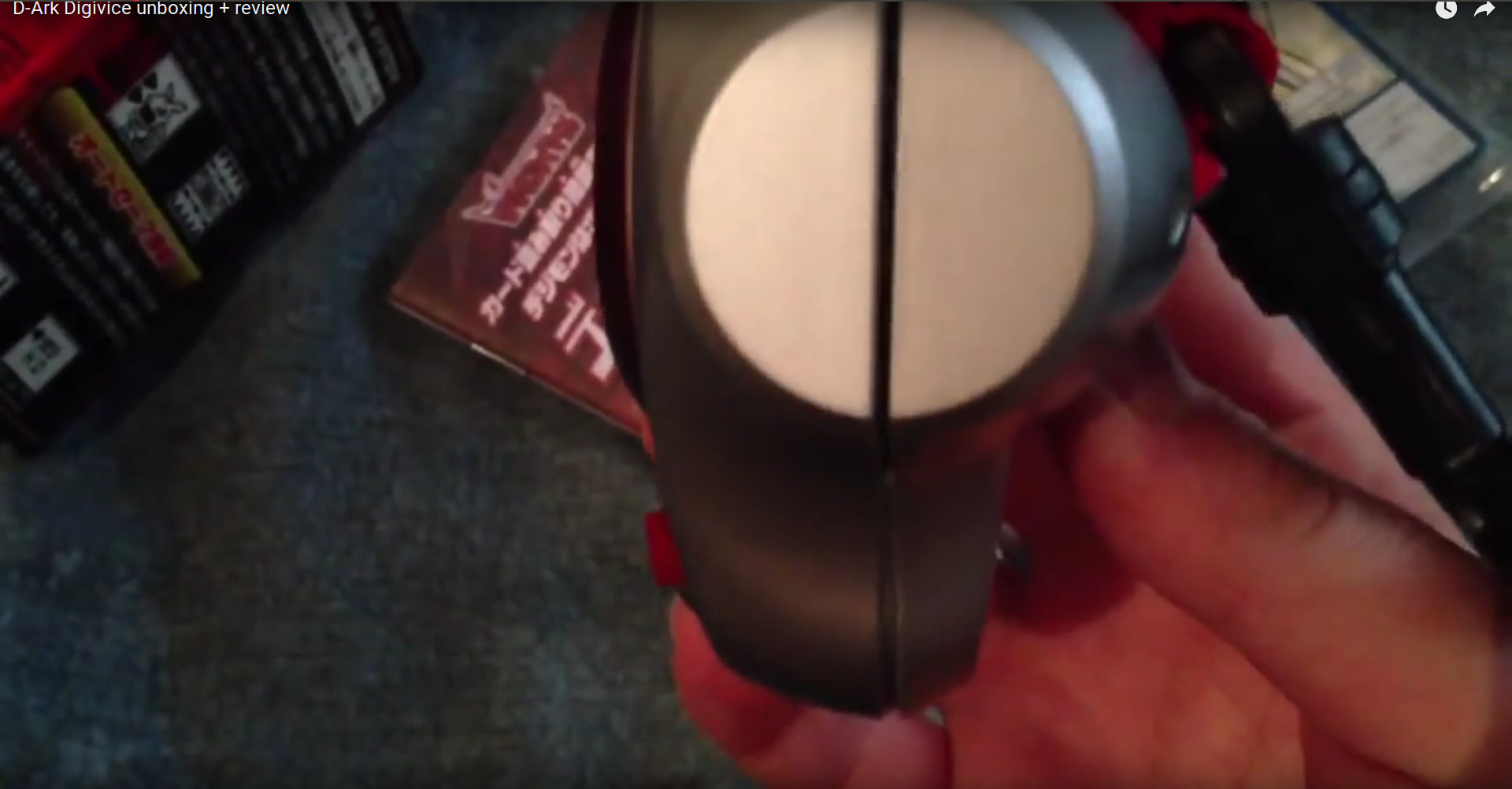
If you’re making that mess to get the forms first, they’re not correct if it’s this device you’re modeling. From the side, it’s closer to a full circle
The device is made of many parts. When you’re modeling the structure for it, don’t try to make it as one piece but many that intersect. Interconnected parts could start as one surface, and then split to get different details on one half, which in turn makes the connection point match because they started as one piece. That can simplify the structure of each part and make it look more realistic.
Even if you have to connect the geometry for a specific reason, 3D printing, that you can do with boolean operations later by combining clean surfaces instead of making one big mess.
My original reference was the devices from the anime, which appear to be a bit thicker in the lower half. This is roughly the best side image I can find.
It’s hard to find good reference material from the anime, without having to watch through the entire series trying to find a scene that shows the necessary angles; it’s mostly shown front-on or obscured by a hand. I’ve used the real-life devices as my reference material to make up for this. Still undecided whether to push more in the anime or real-life direction.
At the moment, the model is destined for a SteamVR Destination, which wouldn’t have a problem being split into multiple meshes, as I can make one or more separate, super-low-poly collision meshes. I’ve not actually thought about how to splitting up the parts, as my mind tends to see the whole thing as a single object, therefore a single mesh. I’d say the most logical thing would be to make the buttons as separate meshes so that they could be movable, if necessary. Also, I thought about making the cut-out for the power button and keep the “plug” as a separate mesh on the right hand side, allowing me to cut the model in half and use mirroring.
I’ve not had a lot of luck with booleans, and I’ve found I often get poor results. If I remember correctly, they have issues if a mesh is not completely closed.