Hello everyone. I was wondering if you would be able to provide a little help as to how to solve a little problem I’m having. Basically, when my mesh is smoothed it results in some weird shading issues, so I’m just wondering what may be the underlying cause. I’ve looked on Google for solutions but I don’t know if the issue I’m experiencing, is in fact, due to the same underlying cause or not. :spin:
I’ve provided a handful of screenshots.
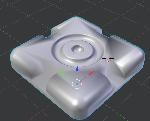
Image #1 shows the shading issues I’m having with my mesh.
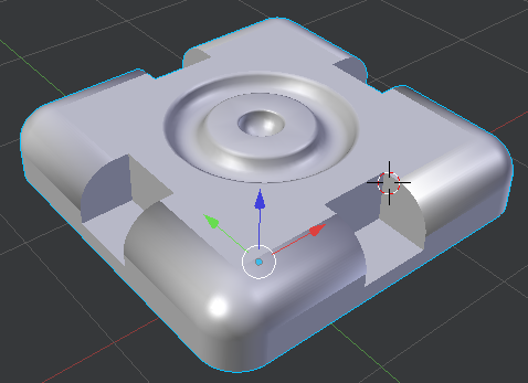
Image #3 shows me attempting to set smooth and flat to certain areas in order to cover it up, but it doesn’t do a convincing job at all, you can see the seams quite easily.
Thanks for taking the time to read this!
Apologies in advance if this is the same as what other people have posted before, I just wanted to be sure!
Thank you for the quick response, this trick has improved the look of the model significantly. I set it to an angle that provided the best overall look for the mesh. However, it isn’t quite perfect.
As you can see in the follow images, there are some creases on the top of the mesh, could this due to the random lines (edges) on the top of the model, if so, how would I go about getting rid of this? Thanks!
The top faces are concave n-gons which don’t get very clean automatic triangulation. Would need to make them convex, ensure they’re on a flat surface, and might also need an extra edge loop so that curved surfaces start from a supported flat surface, or adjust normals to clean them up.
Hmm. I did get rid of the problem by using the ‘inset faces’ option into the areas where I was having a problem, but I don’t know if that is just a dirty trick and just covering it up, rather than treating the root cause.
I believe the surface is flat and that the normals are fine. I don’t suppose you could elaborate a little further, could you? :spin:
You’re getting this problem because you don’t have good topology. Autosmooth is fixing it because the angle is sufficient that it’s marking an edge as sharp, but you’ll want to know about topo for when that doesn’t work.
Inset faces is helping because it’s creating a control loop. In a way, that’s hiding the problem, but the reality is that no model is ever going to have normals that interpolate perfectly, you’ll always be hiding the problem to one extent or another. By moving the control loop closer and closer to the edge you can limit the apparent visibility of the issue.
There’s a lot written on good topo, and you should be able to find info with the right search terms (topo, retopo, topology). The characteristics of good topo are:
Evenly sized, square-aspect quads.
No 6+ poles.
Smooth edge loops that reflect your geometry-- ie, edge loops blend smoothly from circle to square.
Smooth shading tries to hide the edges between faces. Where there’s an angle between two faces, it changes the shading to make it look like one continuous surface. Vertex normals, which are at a median point of the two, are used for the shading.
Adding a curvature with bevel keeps the top faces flat as they were, but with the first angled face it changes the normals, and smooth shading starts to smooth out the angle between first beveled face and the top faces.
Adding a perimeter loop adds an extra face next to the first beveled one which is at an angle. The smoothing is now constrained to that narrow face and the rest of the faces on top are unaffected, because there’s no angle change between that narrow face and the rest of the faces on top.
Alternatively if the normals are adjusted so that there’s a very little to no change for the flat faces, it should also prevent shading artifacts on them.
Cutting the shading works by splitting the normals (auto smooth) or by splitting the geometry (edge split modifier) which also doubles the normals.
I could but at almost 5k posts, I’m not very motivated to answer posts that hide information by cropping the screenshots and that don’t include an example .blend. The file is the fastest way to look into a problem and also gives a headstart for illustrating the answers, which cuts down writing time. Most importantly it cuts down unnecessary guessing. I might answer when I have something to contribute, like this one, but most threads are big waste of time because of lack of information, and because many users don’t come back to even check the answers.
@JA12: Thank you for taking the time to respond, I really do appreciate it.
This was certainly a big wave of information with quite a number of technical terms thrown around. At points it was hard to keep up with what you meant exactly, nonetheless, I value the fact that you responded in detail!
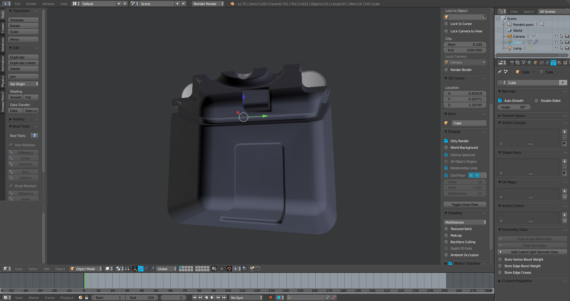
Even with autosmooth on, I am still experiencing these shading issues in some instances. I’ve uploaded a screenshot highlighting where the issue is, I’ve also uploaded the .blend file. If you’d care to look at it. I’m eager to see how you would rectify this issue yourself.
Also, what were those blue and red lines in your screenshots, were they a part of your solution? What exactly solution did you use yourself in the screenshot you provided, and can it be used for mine as well?
Thanks again, in advance.
EDIT: @RayVelcoro: Thanks for the link! I didn’t see your post when I first replied. I will be sure to check it out, although I would prefer a solution that didn’t require the use of add-ons, preferably.
Very well. Regardless, it is unwanted and I would still like for it to be smooth like the rest of the other faces, if possible. As it is rather distracting and untidy to look at
There are interior faces, non-manifold mesh error where edges are connected to more than two faces. That’s a bad one because all of the mesh elements should be connected to just one surface, and that describes more than one, and tools don’t know which they should follow.
After removing the interior faces and marking high angle edges as sharp (ctrl+E -> mark as sharp), you could use the addon Rayvelcoro linked to. It’s a fast way to add custom normals that cleans up the shading. Custom normals are stored in object data properties where they can be cleared. It also overrides the auto smooth angle.
The inside surface has a lot of self-intersections and should do something about those at some point
There are concave faces. Those seem to triangulate ok but if it’s going to be UV unwrapped, you really want to get rid of them. N-gons, concave or convex can already distort when doing a normal UV unwrap but the automatic triangulation on concave polygons can mess things up
So now if I understand you correctly, I just need to add mark edge seams. What does this do exactly? Doesn’t that have something to do with UV Mapping? And after that, create custom normals to clean up the shading?
Sorry for the constant questions, just making sure I understood you correctly so I can get it right! Pheww, okay. Almost there!
Words cannot thank you enough, JA12. I’ve learned so much from that video, thank you for taking time out of your day to do this. It really does help and I appreciate it greatly
What might be hidden between the posts is where the .blend revealed a problem in the mesh (interior faces) which wasn’t in the screenshots previously, and would prevent the addon from working. That’s how it saves time.
Didn’t really answer this, just pointed where normals display options are.
Normals are directions. Vertex normals average automatically, and face normals get calculated from vertex normals to get the general direction of the face.
That doesn’t say much, so a practical example might tell more. Polygonal modeling is approximation of curves and surfaces, straight edges and flat faces, and it’s a surface type modeling paradigm. What we’re supposed to model is an intelligent approximation of surfaces that enclose a solid, using polygons.
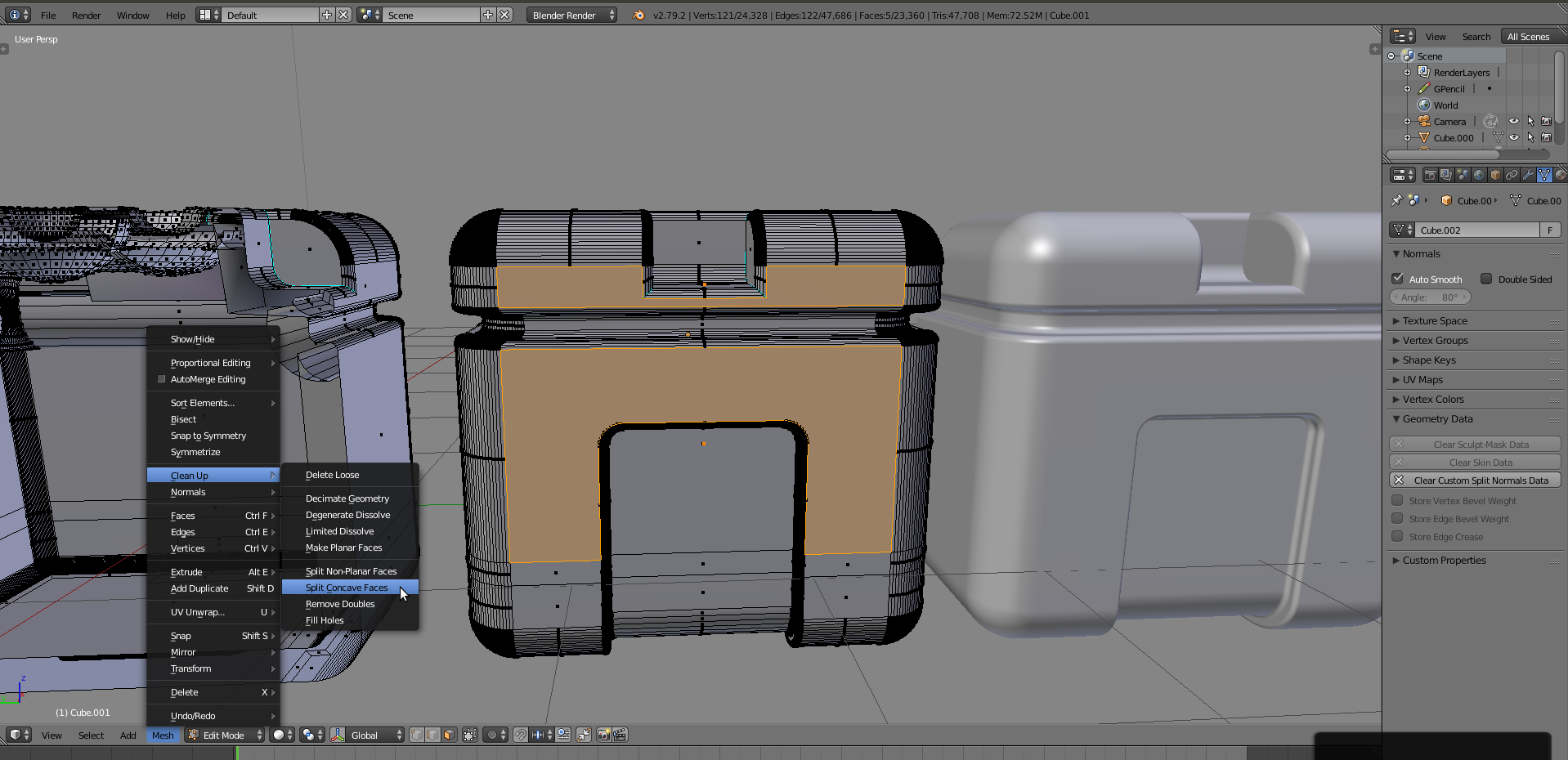
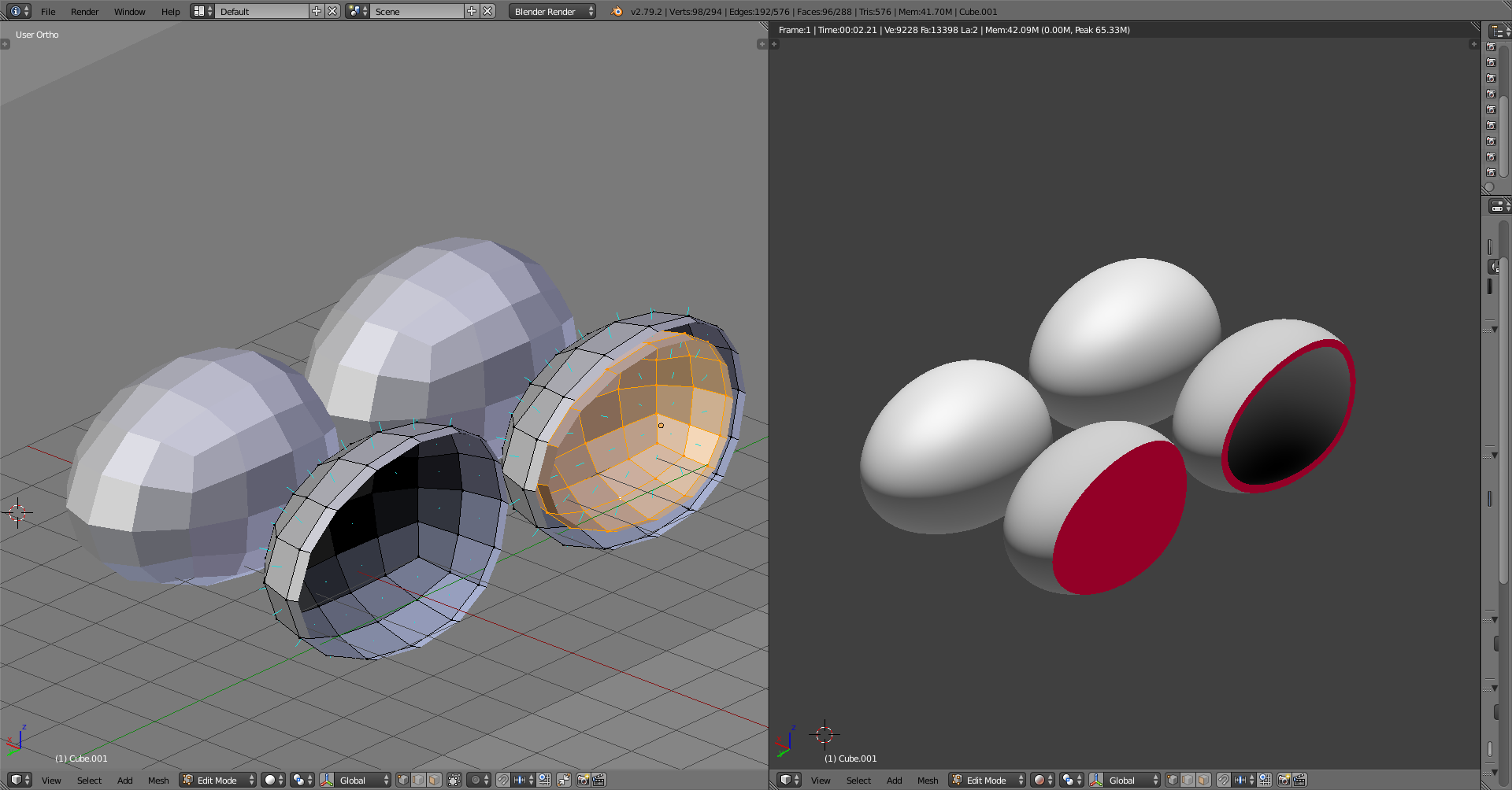
If one is modeling a plastic egg for 3D printing, it could look something like this
Left viewport: approximated surface for solid and hollow model, whole model and a cutout
Right viewport: same with refined approximation of surfaces with subdivision surfaces.
Red color indicates solid.
Foreground model only has one surface. How does the printer know to fill the 3D space with plastic just for the egg, instead of filling the whole room with an egg-size air pocket? With normals. One of the uses of normals is to define the side. The vertices, and therefore the shown faces, point outside. We’re describing a solid by modeling the surface that encloses it, and the normals define which side of the surface the solid is (the inside).
With a hollow model there has to be two surfaces. One on the outside, and another on the inside. Because their normals are set to point away from each other, the space between them is solid.
Normals are also used with smooth shading. When their angle is adjusted from the default average, it changes the shading without changing the structure, which is what was done with the addon. There are other ways to do it but for that it’s the fastest.
The definition of modeling surfaces that enclose a solid also leads to another point. All mesh elements (vertices, edges, faces) need to be connected, and the connected ones need to be part of one closed surface. Or in other words, manifold. All the ways you can connect them so they’re not make the mesh/model non-manifold.
Thank you for providing a further explanation. Just to update, I have resolved the issues I was having earlier and the model looks perfect now. I also learned a few new tricks from watching your videos, these will greatly speed up my modelling process! Thanks again, JA12!