OK so I could not resist this from my sick bed!!!
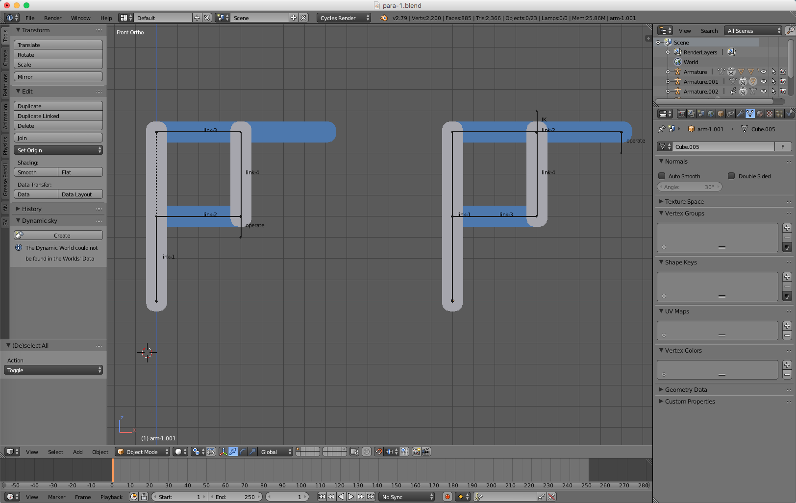
Basic parallelogram constructs are these, depending on where you want to operate it from, either far end or near knuckle - this is your basic “Pantograph” drawing aid:
As for the pallet loader issue, I think everyone is over complicating it (dare I say that in such exalted company :o) This is, after all, the basic JCB Back-hoe rig. All you need to do from a 360 digger, is add the vertical pivot bone on my rig and then get the IK settings right for each bone, the basic arms you lock Y and X in my case as they rotate around Z to work - then you lock X and Z on the pivot. You can then move the target (“operate” bone on my rig) in the XY plane and the base will always line up where it should, i.e. pointing at the “operate” bone, with the need for Track To’s, all sorts of constraints here and there, empties here and there - am I over playing the point here? :rolleyes:
So here is the rig, I have added all the other links, based upon my parallelogram theories so I think I have everything in there working as it should:
You can use this principle for any type of robotic arm, no matter where or how it operates, to add more hydraulics, just repeat the stuff for the lower cylinder fitted to the head tilting mechanism. To operate this rig you only need to move/ rotate the “operate” bone, nothing more nothing less. On these systems incidentally, please be very aware of IK chain lengths and IK properties of ALL the bones in the chain.
Here’s the blend file: para-1.blend (672 KB) As with all my blends, just press Play to see it all working. Then take it apart to understand it. 
Now, I shall take a look at your file, I didn’t before I did mine as I did not want to prejudice my thinking as I have a mental picture of exactly how I do this. I will comment on your file once I have had a good cough, some medicine and a sleep.
Cheers, Clock.
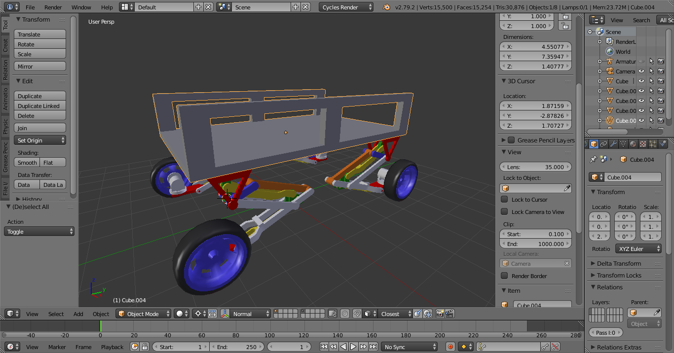
 Was inspired by some warehouse robot stuff I saw as a WIP in another thread on BA, so I figured it’d be neat to come up with something simplified to try and work out the principles of the linkages it uses. And of course IK controlled, in order to make working out the motions a bit more easier. In this case the pointer being the moving end and the base would be anchored somehow.