Ok, I took a break from Blender and then took a while to gradually understand exactly how to reproduce the geometry in the example file. I wanted to figure it out properly by myself if I could, and sometimes that took a surprising amount of time before realizing it was simpler than I’d thought at first. I now think I’ve managed to go through how it was done and assume I understand a much better way of approaching these kinds of shapes. Posting my results below…
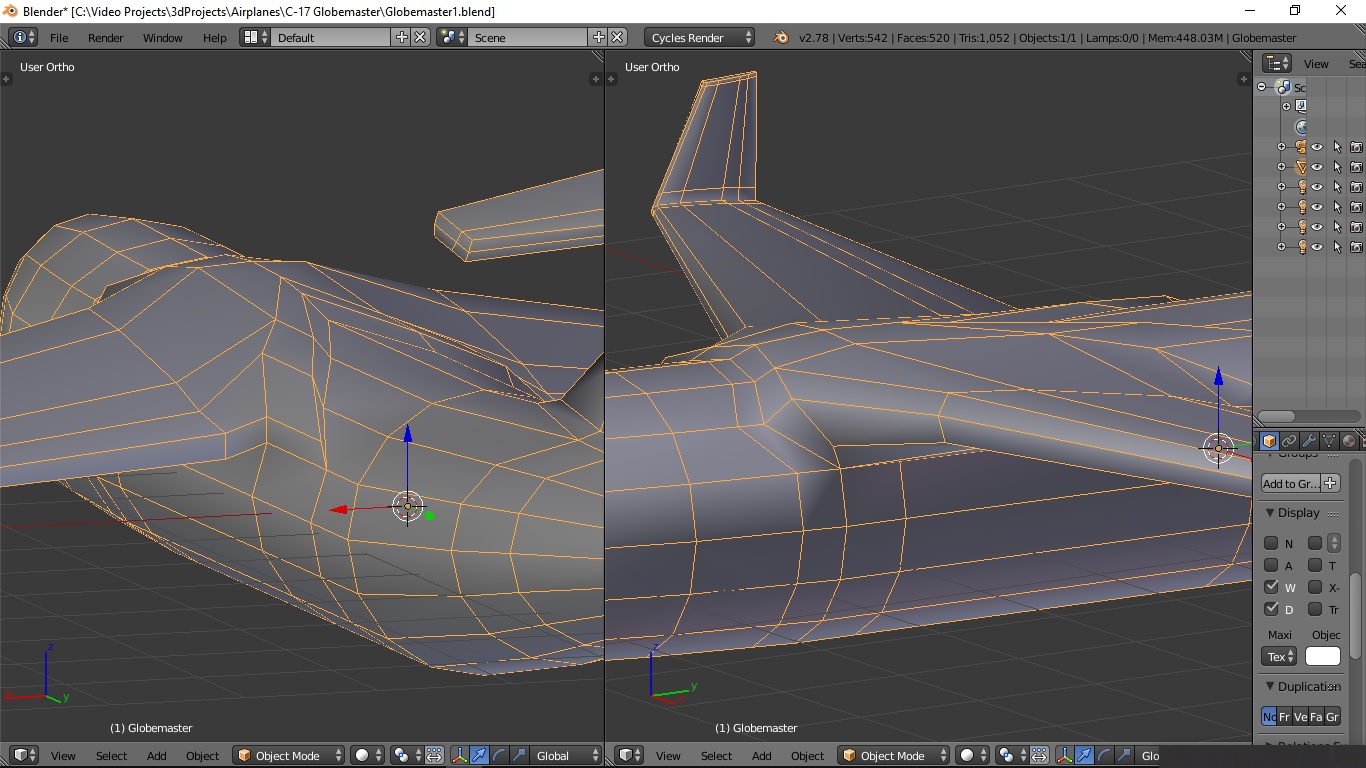
I began by working backwards from the example and trying to recreate what I assume the fuselage looked like before any extrusion, in terms of the edge loops and vertex positions it had. At least I managed to discover the Grid Fill tool during all of this, which I didn’t previously know existed but I’d been looking for a way of doing exactly what that does so that’s useful.
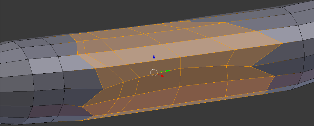
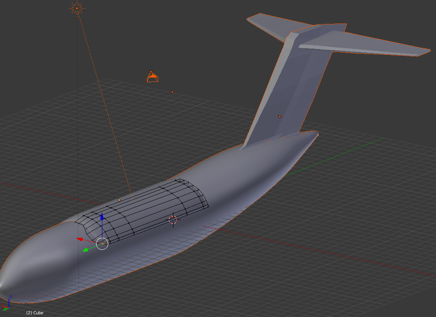
You can see the result below; I’ve tried to smooth it all to a roughly consistent cylindrical shape but obviously it’s a bit iffy. Still, I assume this is roughly what the stage before any extrusion should look like as far as number of edge loops and vertex positions are concerned?
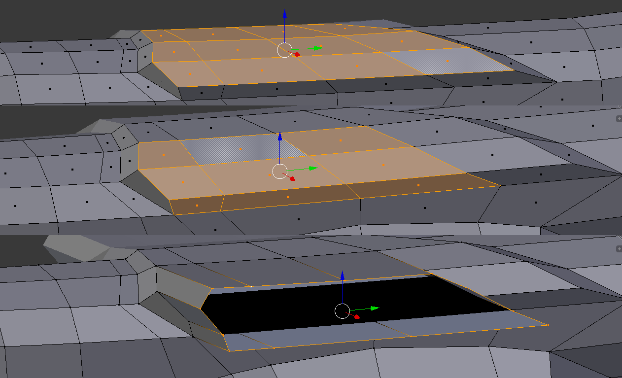
For the wing root, I selected the top faces, extruded them out and then pulled them inward a bit to create the gradual curve. Then I moved the frontward-most top vertex nearest to the side forward a bit (this took me far longer than it should have to realize what had happened in the example... sheer inexperience). Then I selected the appropriate 9 faces on the side and extruded along the X axis (again, I at first figured out how to approximate this by deleting 4 vertices and extruding the surrounding edges but it didn't at first strike me how to do it by simple extrusion...). I then cleaned it up by deleting the end faces and aligning the vertices. I noticed I had to dissolve 2 edges running along the top of the wing then to achieve the exact same topology as the example; I assume it's just good to remove all edges that seem unnecessary when you're trying to get the very basic shape, and that they would have also been manually removed for the example? Otherwise the topology must have been quite different before the extrusion, but I can't picture that since it's just 2 edges running width-wise across a single length-wise edge loop... probably not important either way.
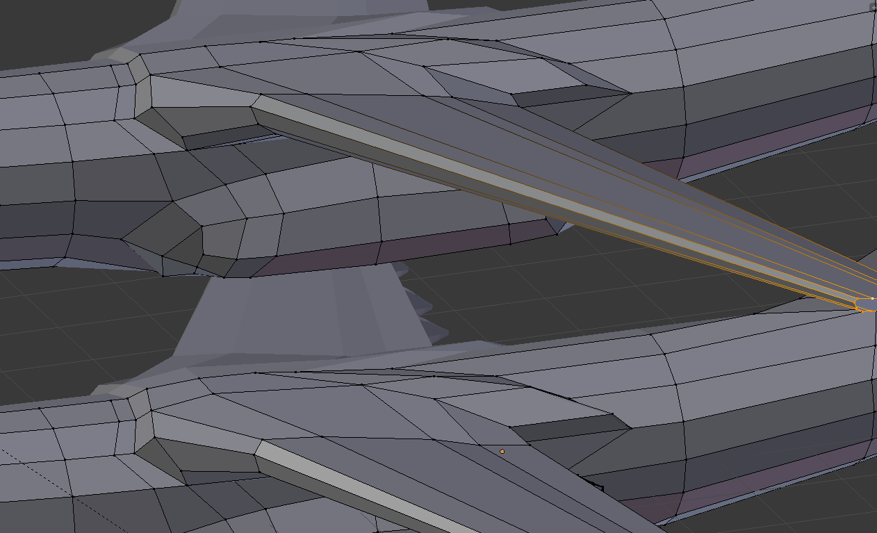
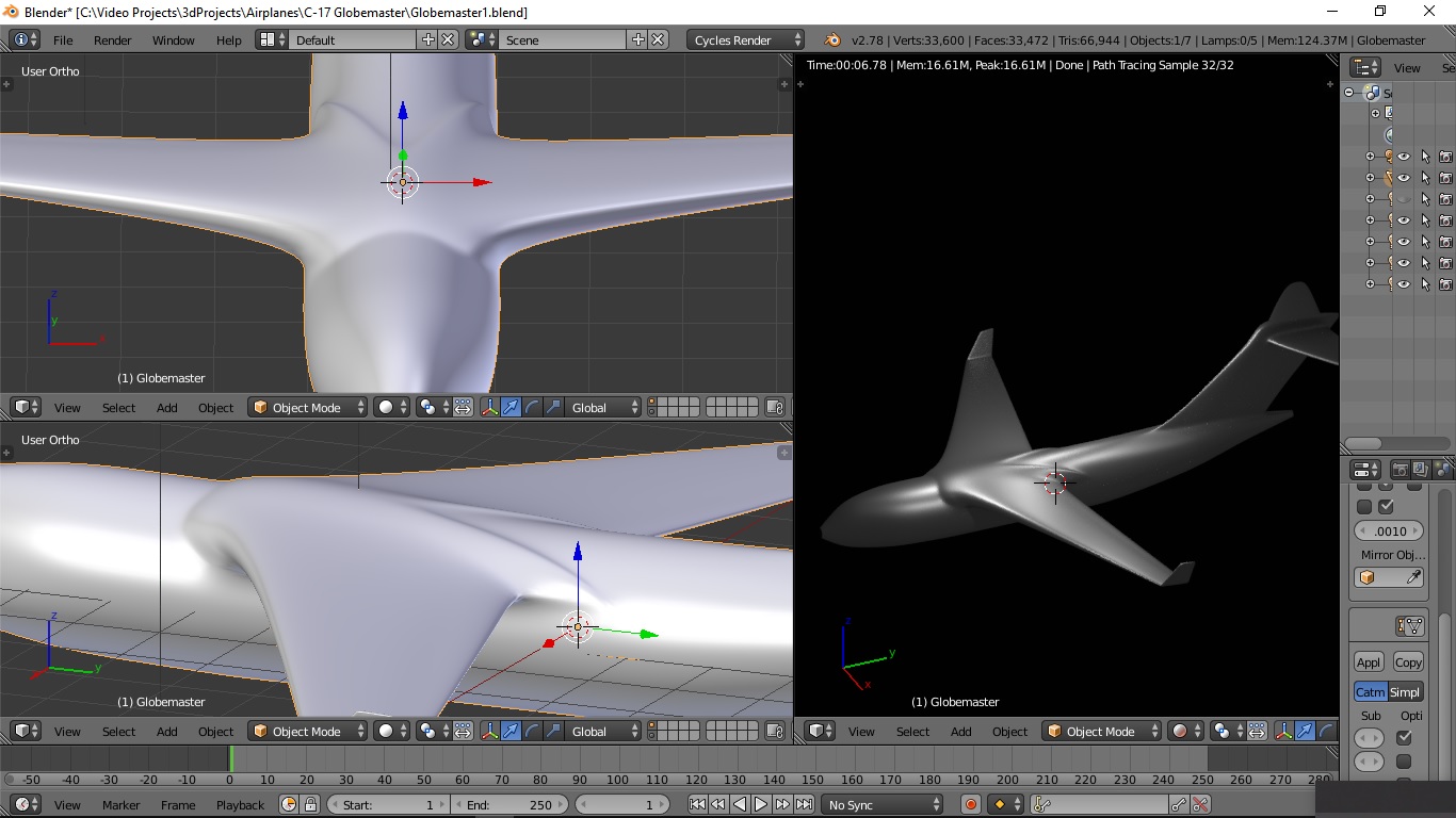
I extruded the wing stub out again to the full length of the wing and scaled it to taper like a wing, then just cleaned it up by moving a few edges and vertices around by hand until it looked more like the example.
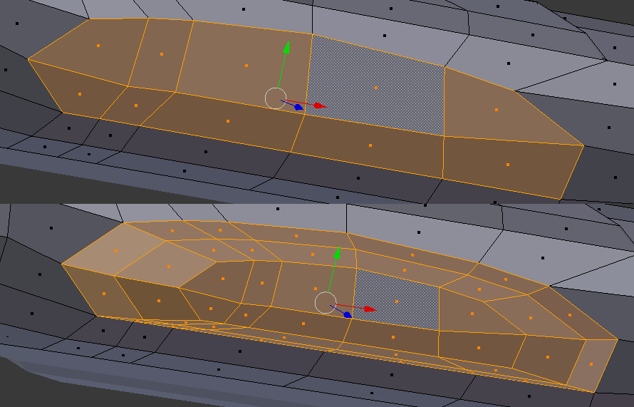
(In the below pic, my attempt is on top and the example is on the bottom)
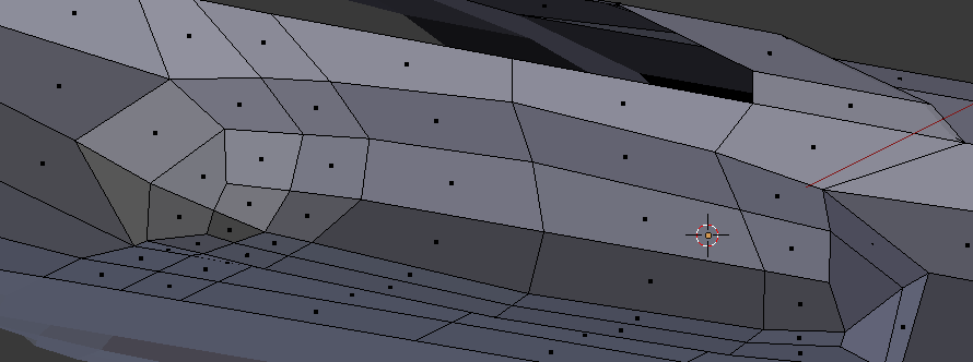
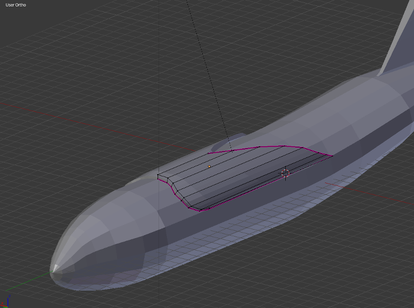
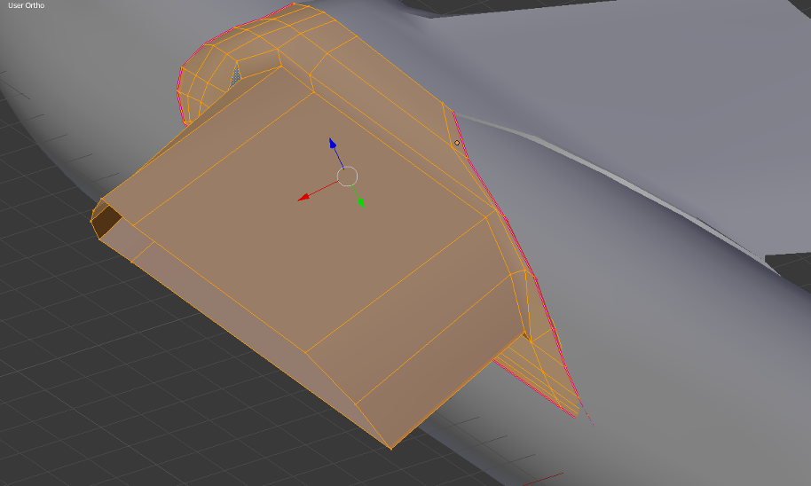
For the bulge, the inner loop especially confused me at first because I wasn't sure how to create that with extruding alone.
Then I just extruded twice and scaled inward each time, counted the faces and they were the same amount as the example so I assume that’s the same topology and all I’d need to do is pull the vertices around until they look about right?
All in all, does it seem like I have a good grasp of how it should be done? I think I've learned a few things either way.
Oh and something else I noticed but couldn’t find the answer to: I tried changing the render engine to Blender Render in the example file (to see what it would look like in low-res without any AA like I was experimenting with some other models) but the render always turns out completely grey. I messed around with the camera a bit and did some searching but I wasn’t able to get anywhere; it only works in Cycles. Why is that? I could always render my own models in both Cycles and BR, so I assume there’s some setting that’s been changed somehow that prevents it from working with BR?
 but for the wing part it was two loops added to adjust the strength by sliding them closer or further from the extruded geometry. And using creases are a nice ‘cheat’ and work well when you do not want to add additional geometry, kind of helpful for hard surface modeling but for organic modeling it isn’t really a preferred method as well as with animation. Best advice is keeping the model simple at first then adding the detail once you got a base mesh laid out.