Ok i ve spent a good part of the last week-end trying to make further improvements to a suspension construction created by Weaveaser and that i modified.
The pb is the following:
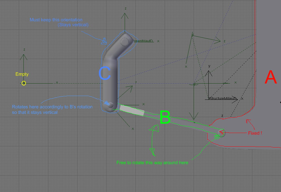
(I ve tried to reduce the number of items to a minimum for clarity’s sake: the real file contains many more objects, most are hidden here.)
The C object has to mimic the empty’s Z coordinates.
BUT, because it is tied to B and B is attached to A (via) it also has to move lateraly in the x direction.
Do you get it ?
The junction B/C describes a portion of circle whose radius is the length of B more or less)
An important constraint is that C has to keep perfectly upright at all times !
I have tried with constraints only, with B pointing C’s bottom and C copying an empty at the end of B but it is a kind of “vicious circle” and the whole construction moves with a delay, B being unable to follow C quickly enough !:eek:
I tried to used bones to and it was fine up to one point: if there is one bone per item, articulated together, it is simple enough to have B rotating nicely with C at its end copying B’s rotation in negative so that it stays upright. Everything seems fine, with C moving gently along the x axis as it goes up and down. BUT HOW DO I THEN MAKE C COPYING THE EMPTY’S Z VALUE ??? I i put a “copy location” contraint to that bone, it interferes with the rotation duty it has.
I ve tried IK…no success.
I hope i ve made it clear.
If not dont hesitate to ask questions !
um, im not 100% sure what you’re trying to do, but how about an armature setup like so:
the green bone would correspond to part C in your diagram, the middle bone to part B and the bone farthest right would correspond to part A
with that constraint, it keeps the top bone upright when you rotate any other bone
hope that helps
Yes that is a good start, BUT the green bone has to obey to the empty and copy its z value, so that when i manipulate the empty up, the green bone slides up too…
I just used armatures just because it was less work that way … I think I understood your problem … but if I didn’t get it right please point out what doesn’t work for you …
But if I did I just want to point out that you can always add parent/child hierarchies to any object, where the child will inherit the transform properties of the parent object . That is basically all I did to get the C bone to copy the Z transform value of the empty, by adding a child empty that bone B followed by either the track to or the IK solver constraint applied to bone B, where bone B is the parent of bone C … (this explanation may confuse you more … look at the file and if you have any questions post them …)
But the two “solutions” (if they are that for you) are not the only ways of doing this . I just set up two easy possible solutions with different constraints … in fact setup two could be considered “old school” as the limit rotation constraint was only recently added …
Thanks for taking the time to create those examples !
That being said, i truely appreciate what you did. Very clear examples !
I must say i got exactly to that point: everything works smoothly in appearance. BUT, and that is where i am stuck: if you look closely, C doesnt move up and down as the empty does.
It either moves quicker or slower depending on the empty’s x location, because of the “point to” constraint.
Do you see what i mean ?
What i need is that if the tip of C is, say 0.2 BU above the empty at start, it stays that much higher precisely all the way !
Through this C object pass an axis for the wheel of my suspension: the wheel follows the empty EXACTLY
I cant have C moving faster/slower than the axis…
A tempting solution would be to have the second empty being locked in the x axis under C, but that is impossible: C moves along the x-axis as well… :mad:
And if the empty B points to is parented to C’s bottom then you get lags and incoherences as i mentionned in the 1st post.
OK so B is supposed to be a suspension system of some sort … Kind of an odd orientation for shocks … that got me a little confused …
Well there is an “easy” solution to this : use the Stretch to Constraint on bone B targeting the Empty_child … But I say easy only in that you will get the motion you want out of the rig but you will have to add extra bones for proper mesh deformation/control and also use the “Hinge” option in the Armature Bones panel (before the “Deform” option) for all the children of bone B … Well you don’t have to do the extra bones thing but if this supposed to be a real life analogue to a suspension system then it is a good idea … You could just model a spring that was controlled by bone B and it would squash and stretch pretty realistically but usually there are some rigid parts in shocks .
Notice that I got rid of the constraints in bone C - they are not necessary because of the hinge option being turned on . You need to have it on because otherwise C would stretch and squash along with B because C is the child of B . When you turn on the hinge option the child bone does not inherit the transform properties of the parent .
The second version has some basic meshes parented directly to the bones and also additional bones needed to deform/control the meshes properly . Be sure to check what the parents of the new bones are in the file in Edit Mode for the armature . Carefully planning the parent/child hierarchy will prevent you from causing cyclic dependencies (the lag you experienced before) when you add constraints that seem to point back the parent bone .
The new bones are kind of hard to select with the mouse because they are somewhat hidden by the larger B bone . If you have trouble selecting those, open up the Outliner and select from Armature.001 the bones A.001 and B.001 to check out the constraints that were added to make the cheesy shock I modeled move properly .
Hope this solves it …
EDIT : Oops … I made a slight mistake on the second example … I forgot to reset the Rest Length for the stretch to constraint in the second example after moving the Empty_child2 to do some adjustments so that now Object/Bone C is not quite center .
Actually I guess this is a good thing … The stretch to constraint can get a little buggy if you change the transform properties of the constrained bone in Edit Mode or just move the constraint’s target . It took me a while to realize that when I first started to work extensively with it a while ago … So maybe this mistake will prevent you from tearing you hair out later …
To fix this first select the armature in Pose Mode and turn on the Rest Position option under Deform Options in the Armature panel . Then select bone C and Shift-S -> Cursor to Selection, then select Empty_child2 and Shift-S -> Selection to Cursor (you can also use this point to move the parent Empty2 to another location if you want but move Empty2 first as Empty_child2 will just follow its parent and you will have to do the second part over again) . After you have everything in position select bone B and then go to the Constraints panel and hit the “R” in front of “Rest Length:” . When you do that the rest length value will turn to 0.0000 . Now go back and turn off rest position . Object/bone C should now be centered and move up and down only along that X coordinate when you move Empty2 along the Z axis .
If you are curious as to what the true “rest length” of the bone should be just select bone B again and look . You would think that it should be the length of the constrained bone but usually it is not because it also takes the distance of the target in to account … But if you want to force it to be a certain value you can just type it in manually … and of course the values are all in BUs …
Waow !:eek:
I feel bad now… I must have taken you quite some time to produce such an exhaustive answer !!!
Your most recent answer got me closer to what i want: C obeys the empty much better. However there is a major drawback. In fact B is supposed to keep it’s length, it isn’t meant to strech like you did Here you can see what i strive to
In fact what i need is a crossing of your 2 answers: C follows empty exactly and B keeps its length…
Pffffffffffff…
There is also a video on Youtube of the suspension i try to improve:
B is the fork type object at the bottom,
C is the piece trough which the rotating axis goes.
As you can see, it seems to work fine, except that it uses one of those cyclic dependency and it makes it “imperfect” and laggy
I dont want you to spend 3 more hours on that one : you surely have better things to do !
I dont know if what i want is at all possible after all…
Gwentiv don’t feel bad … I’m still learning this stuff and trying to help is a great way to be exposed to problems that I normally wouldn’t get exposed to . And I am glad to help when I can .
But back to your problem … Well yes I think it is impossible but not because of anything related to CG or Blender but because the real life analogue wouldn’t move the way you are wanting the parts to move … Even in the short video you showed the C part does travel across the X axis with the rotation of B, it just doesn’t seem as extreme as in the first version I posted, the rotation of which you noted in your video . But you can adjust the apparent rate of C’s motion to the empty by simply moving the empty closer to C along the X axis (don’t move Empty_child) . The closer you get with the empty to C the faster C will move relative to the empty … so if you play around with it a bit you might get the apparent synchronization between the empty and C’s motion . But you cannot get rid of the rotation that C inherits from B if B must remain constant/stiff . It’s just not mechanically possible .
Even in the Youtube video if you look carefully the “Fork” isn’t really constant . There is some “give” that is occurring at the joint where the fork meets the axle body …
So if I were you I’d just start arranging the entire setup -shocks and all and add the wheel etc. and figure out how to make that work together rather then try to bend the laws of mechanics to your will …
Gwentiv don’t feel bad … I’m still learning this stuff and trying to help is a great way to be exposed to problems that I normally wouldn’t get exposed to . And I am glad to help when I can .
@ Vertex : okok
Sorry i am late to answer.
I am a bit disturbed by the fact it seems physically impossible to you.
My instinctive feel doesn’t make me think it is…
Any way i think i cant get what to work so i 'd better turn to something more realistic: i think i ll change this suspension to a double-wishbone one once i’ve got the time… Maybe this week-end ?
Thanks for your support mate !
I ll keep you posted !
I have yet to get it to work using just normal drivers, which baffles me, because it should work.
Anyhoo, I’ll keep working at it and let you know if I come up with anything.
UPDATE 2:
Got it! It doesn’t work for bones, unfortunately, since they use quaternions instead of Euler angles, but it works for objects, at least.
I dont know how to programm in python (and in any other language by the way) so it looks like black magic to me !
I cant get this script to run on my Blender: i guess i must have the SVN Blender for that ?
The 2nd solution is really impressive though !
I didnt know there were such possibilities with drivers.
I think i must learn Python !
How long did it take to master python ?
Thanks again !
I hope Vertex can see that: we’ll have learnt a bit from that !
I didnt know there were such possibilities with drivers.
I think i must learn Python !
It actually has a lot less to do with Python than it has to do with math. In this case, a solid understanding of trigonometry.
Almost all of the Python in the first solution is just fluff to make it work as a pyconstraint.
The Python in the second solution (with drivers) is actually quite minimal: I just used it to express a math formula. (It actually looks more complicated than it is because I had to convert between radians and degrees-divided-by-ten.)
How long did it take to master python ?
Eh… my answer will be skewed from what you should expect for yourself, because I have a fair amount of previous programming experience. Also, I’d hardly say that I’ve “mastered” Python.
But to get to where I am now, maybe two or three months of off and on scripting? I never sat down and actually “learned” Python, so to speak. I just sort of picked it up as I went. When I ran into something I didn’t know how to do yet, I looked it up.
Boy is my face red … from rage !!! … just kidding … I guess if i had to get my “come up ins” better it comes from a Peach project member … But you better make Peach very very very funny Cessen … Or at least make some narrative sense … But I can live with it just looking “good” like the last one … (Or can I ? Uh oh I think I am getting filled with rage for real !!! … must not … turn … green … just got car fixed … ! )
But then again how many people here other then Cessen would come up with using arc sine (I assume thats what “asin” is in python … before I embarrass myself again ?) from trig to write a one line Python driver to make something (I still find counter intuitive from a mechanical level) work ?
But of course that is what is cool about this forum is the various experiences of the people who participate in this from every newcomer who approaches a problem in an “odd” way to people who have a lot of experience and the occasional coder who tries to help once in while …
But I’m glad to know that the custom pycontraints will be available soon (is this going to be in 2.45 ?) … And I too should get myself into Python (I also know a few programming languages and was waiting for Ideasman to complete - mostly as an excuse - his revision of the API, like I am mostly looking at Blender code in bits waiting for V2.5 … but then again the Ghost Refactoring is on hold … so also another excuse I can use to do nothing with regard to coding …) … But then again if you have any programming experience at all you know a lot of it is “looking up” stuff until the stuff sticks and most of the math stuff is mostly the same (in terms of notation) across all “modern” programming languages .
Thanks Aligorith ! I did download the SVN with the PYConstraints … but between all the various builds I have now it’s starting to get a little confusing … in a good way of course .
![http://dominomf.com/smcfiles/Jeepster[]_armaturehelp.JPG](http://dominomf.com/smcfiles/Jeepster%5B%5D_armaturehelp.JPG)


