@Alain, maybe it’s a bit early to provide library as data model is likely to envolve, making those presets obsolete.
As a side note, the “geos” branch does include import/export ability for presets (.apk) files wich are zip of your presets folder.
Windows can get complicated, to generate, if you imagine the differences under basic criteria:
types by opening: casement, sliding, hung, awning, pivot, folding, etc
types by material: wood, aluminum, plastic, steel
The above categories usually have distinct profile characteristics. According to the above eg material, wood profiles vary significantly from aluminum and sliding window from casement.
Then add to that complexity, the difference between manufacturers, or custom designs.
How many parameters? and more variable: how many profiles to be included in the program?
Well the essentials or almost always components shared by all are: the frame, the sashes, the glazing and then lintel (inner, outer), inner trim, outer frame. These place demands on wall cut-outs.
A common workflow is to get the best/closest approximation by the addon topologies and then kill the parameters and customize further.
What if instead of using a program “typical” profile (-es) and assigning parametric dimensions, the program allows the user to attach any profile, for each component and extrude that along the window outline path: a path for the frame, paths for the sashes. The curve modifier, would be the main Blender tool for this. The curve would have the essential parameters that “box out” the shape. The user would have to be restricted in placing the profile origin properly and either the user would input the “container” dimensions of the profile or the program would “fish” them out of the geometry.
Btw Stephen: how do you generate the geometry of the window components?
What does he mean? how can one add their own construction details?
I think it cannot be any other way for technical docs and for construction when we say the window dimensions, we mean that! whether there is overlap of insulation or cladding is indifferent. The Window width in Archipack is inconsistent with the industry definition and as such misleading to architects setting up their windows with the addon.
Archipack 1.2.8 is now part of addons so you’ll find it in 2.79 release. You may also setup and use this addon in Blender 2.78x
You will also find installation and usage instructions in the Wiki.
So it should work fine with 2.78 (I use 2.79). Because it is new addon it was not included (I think in 2.78). To download from Github, switch from the Wiki tab, to the Code tab, download and install from file (Blender, User Preferences, Addons)
Hi, @Mauzz, it was originally done on 2.78, and i take care of not using 2.79 fancy new features so it should work. Please let me know if you encounter any issue.
@Christos,
Archipack’s windows follow architectural definition of the size wich is the dimension of the structural layer opening,
so when an architect set the width/height according blueprints he/she get the right window (currently staggered one with overflow).
So i think we talk about the same thing, but overflow is somewhat misleading.
When you “manipulate” the window with hole done, you’ll clearly see what size is about.
With all respect (plenty respect for such work!), I am convinced that you are wrong: there are certainly many ways and different details to finish a window and a facade, however in almost all cases the width and height are measured in the “structural” layer, Archipack does not give window dimensions at the structural, but at the facade surface.
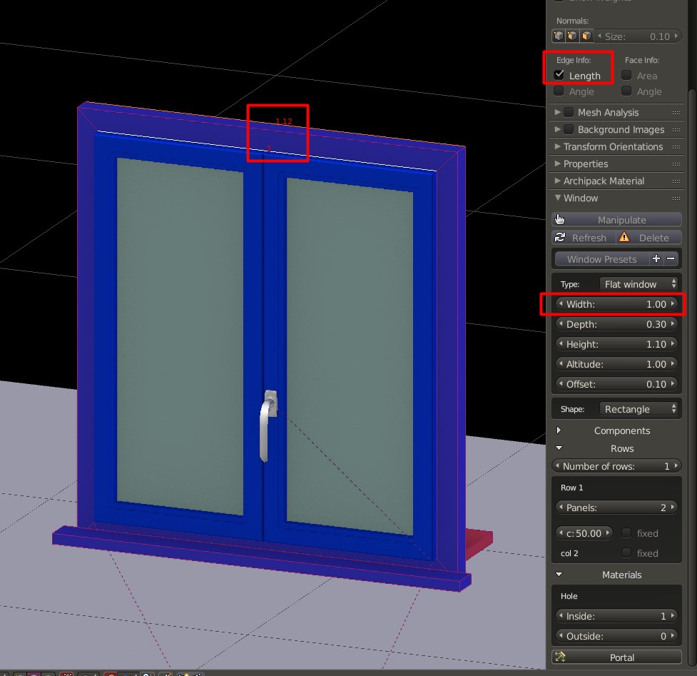
To illustrate the point I used a material colored blue for the window frame, Archipack calls the window width 1.00m where the blue window frame is 0.06+1.00+.06=1.12 (see parameters on side menu). Can you imagine ordering a manufacturer to send you 1.00m wide windows and meaning 1.12? would you label this window on drawings and documents 1.12 or 1.00? I would label it 1.12 on the annotation symbol and at window schedules (the only drawing where I might put a dimension of 1.00 is on the elevation)
Notice that a window with Archipack window of width 1.00 measures 1.12 at the frame. (This same window will display an opening of 1.0 at the outside facade, because it overlaps with the wall)
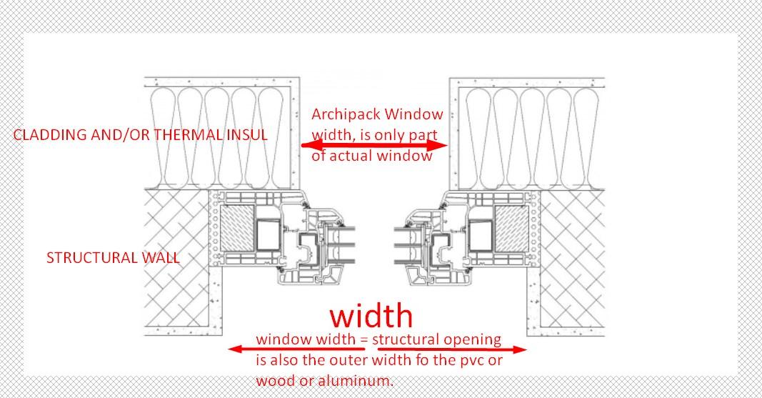
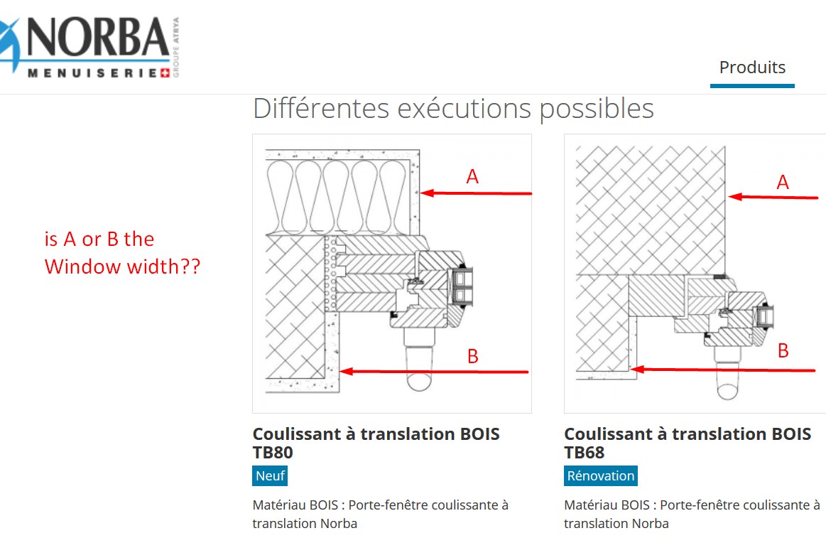
When an architect sends technical docs and most importantly a window schedule to tender, he/she cannot send out a dimension that is not all of the window, one measures from edge of frame to edge of frame. Below is an example from the company Norba, that you linked to. (the comments in red are mine)
You are correct that in their technical documents they show the facade covering part of the frame, but I insist industry standard “Window Width”, as per window schedules, is measured at the structural and in fact even more accurately it is the width of the manufactured window, be it wood, pvc or aluminum and not the part that shows on the facade.
The reason I insist is because I think Archipack is promising because in many ways it is very intuitive and automatic to architects. Contrary, in this case I think, it is totally not according to industry standard definitions.
I would ask other architects to take a look at this post and try Archipack and record their opinion on this.
I’m talking about staggered windows, and the way i’m used to work with them.
As frames size may change across manufacturer, the width we used to use in technical doc is always the exterior hole width (the smallest one).
It’s also the width the builder does use (as long there is no external insulation).
When drawing blueprints you never use anything else than hole width as it is the visible part on final wall and will not change whatever window type you choose to use.
Manufacturer does know the needed overflow (when apply) and then provide the right window for our holes, this apply for staggered and straight holes.
The sample with insulation is somewhat misleading, but anyway the manufacturer has to know the opening left on external insulation in order to provide the right window.
Dear Stephen,
I understand your diagram, but would very much like to see what kind of detail would match, specifically what you call overflow by the manufacturer.
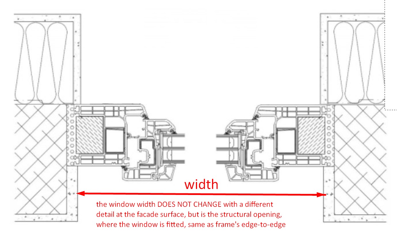
Following are two more details, again from the manufacturer of your choice link Norba of Switzerland, this time with wood (you are correct the facade opening is smaller, but in my experience orders are with the manufacturer frame dimensions, which is the same as builders-tolerances)
Guys, are you sure you are talking about same wall layers? Stephen, your diagram is rather strange. It seems that your structural layer is on the outside and overlapped? Is this right? Could it be your thermal layers are on the inside? That is new to me.
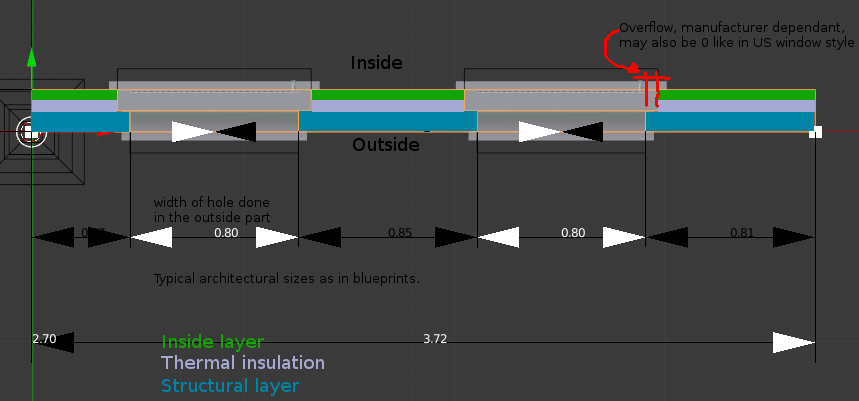
I think csimeon and i are sinchronised with the Norba link you gave but not your diagram. The structural layer is the main wall layer and usually the thickest. It is also the one window usually is attached to since it is the sturdiest (it carries load). If i haven’t been in professional illusion for two decades, the thermal layer is always on the outside. At least for the main part of the continental Europe, and everywhere i’ve seen in my practice. It is thinner and lighter than the structural layer and often overlapped over a part of the window frame to block thermal bridging. Everything according to left graphic in the post above this one. On that image the inside is down, where the window handle can be seen. The engineers and contractors use the dimension of the structural hole for manufacturing as well as masonry, thermal and extra façade layer overlap are optional and is considered a design detail. This is in my opinion the most common type of wall structuring and window installation.
The diagram you have shown is something i have never met in this region. I could be wrong about other European areas or possibly, more humid areas, such as Florida and tropics, where some inversion is needed because of evaporation and condensation. Sorry if i lack in knowledge, this is according to my practice, you are welcome to correct me.
Hi, @Okavango: Yes thermal insulation layer often is inside, between structural one and a thinner internal one. @Christos: dont be afraid, we all are learning from contributions like yours, and as you said it is for the good cause.
The point is not the wall composition, but the way architect do draft mesures.
So when arch people say a 110x120 window it dosen’t rely on the real window size (while matching with straight holes), but the apparent window size from outside point of view regardless layer composition - i might be wrong here, but it’s the way i learned it.
I think the left diagram is misleading, as it is an exterior insulation, (as found in swiss “Minergy” homes) so layers are swapped.
Anyway, archipack size lie on the A side of Norba diagram, “wandlicht” side as said “auf deutsch”.
Difference between A and B is the frame overflow, wich is obviously manufacturer dependant.
Pushed window_overflow branch to test, mostly working - with notable exception of “Top oblique” shape
Find frame overflow parameter in Components->Frame and set to 0 for straight holes.
I do not agree that the apparent is the “real”, whatever that means. “Real” in the construction industry can mean the boundaries and dimensions of architectural elements, are important because they relate to construction jobs, from that perspective it is important that the width be the total width of the “job”, for builder and for window provider and that is the norm for the architect to show.
I may may occassionaly dimension like that while drafting of facade composition, and I still might in an elevation drawing at preliminary phase. In every stage past that, specifying the window relies heavily on its size (by material, by job). Drawing annotations, building schedules and other technical drawings would, in my experience, use the external frame dimension (or that +tolerance for the builder dimension, depending).
That there is a dimension called “A”, does not mean it the window width - the context is important, in fact “wandlicht” literally means “wall light” or the clear opening, which was what I called it, in an earlier post. Though the clear opening is a dimension that may be listed in a window schedule (along with other window properties), THE main dimension, that is on the plan annotation symbols, is measured external to frame.
What seems an overflow to you on the details I posted, is in my opinion, the frame profile, notice that it is a single profile, there is not an additional piece to adjust fit to wall. It could be a frame “extension” or overflow in some other specific wall detail, so PLEASE share a wall/window detail that you think shows your argument (the one “detail” you posted so far, with dimension “A”, is diagram not actual detail). I know that Archipack is not a detailing program, but you see how things are related! Also note that the mesh that Archipack draws as a cross-section of the frame and sash does not suggest any overflow but seems to be just the frame.
By overflow, i mean how much the frame overflow over the wall light, regardless window detail.
So using the new “overflow” parameter of frame, it should now be possible to achieve both goals :
When overflow is 0 the frame fit exactly with the “archipack size”, and should fit your needs.
When overflow is = to frame width the frame will overflow and the “archipack size” is the wall light.
While probably true in a “straight hole model”, it is not when it comes to “saggered” ones !
In the saggered hole model, the builder can’t rely on any other dimension than wall light, and manufacturer know how much the frame must overflow so the frame fit with the hole, so we only talk about wall light and the way windows are attached arround.
Usually window are then fixed to the structural layer and then the thermal and inside layers are built arround.
As a side note, in both cases archipack size should be equivalent to the wall light (with tolerances).
I had a couple of projects developed using Archipack. Today I checked into one of the projects, that a junior architect had been working on. I very much liked the looks of the project and her use of Archipack to get results.
When I tried to edit the drawing, I was surprised to find a very messy layout from her use of Archipack:
there were several “Reference” parents, some nested in each other
several “Autoboolean” objects too
These obviously were created everytime she added a set of windows/doors to be cut from the walls. She did not first create all windows and doors and then cut them into walls all at once. This is the reaseon for the “messy” structure. I am curious to know your workflow.
My approach was to clear all parents and redo the Autoboolean, using the “Interactive” mode. This way, no “Reference” objects were created and no Autoboolean objects.
For each wall I edited with Autoboolean, Boolean modifiers were added named Autoboolean.XXX, sequentially numbered.
I found out that though a wall had only 2 doors, for example, performing Autoboolean added modifiers for every door and window on the project!
My questions:
Consider that a project may consist of several buildings or several stories in one building, is there no way for Autoboolean function to only add those holes to the modifier, that are actually on the specific wall?
Again for the sake of complex projects, is there a way which set of Archipack elements belong to a parent “Reference”?
Why do Robust and Hybrid modes construct an Autoboolean object? (in addition to the modifiers)
Usually i do first create walls using draw a wall, and then add my windows / doors using draw tool (use c in the between to select another preset, and shift to make independant copy when needed).
Also when a window is the active object and you press alt to call “draw tool”, the draw tool will use current window as model.
Barely never using “autoboolean” as draw doors/windows are faster and take care of boolean part.
I only use Autoboolean with walls done using 2d to 3d tool, when duplicating doors/windows by hand, or to make booleans revival after an “apply all modifiers” done on a wall.
1 :
Autoboolean does use wall bounding box to detect wich holes should be in use for it.
I know this detection is not precise enougth, and something must be done to take care of real intersection with the wall.
2 : Reference point
For some obscure “dependancy cycle” reason, a child object of a wall can’t be the hole for boolean (wall will then depends on child via boolean and child depends on wall for her location)
So to break this loop, both wall and hole are childs of a Reference point.
When you either add a window to a wall using draw tool or autoboolean, a Reference point is added if the wall is not child of existing one.
Autoboolean try to find openings laying in the bounding box of the wall, and use them to generate a hole.
3 : Booleans
When performing many booleans (400+ in tests done here) to a single wall, we found that adding more than one boolean modifier to the wall sometimes may fail.
So the strategy to make it stronger imply sorting holes from center to outside, and first join them either using a boolean (interactive mode) or into a mesh (robust) and then using joints holes to perform the final boolean to the wall.
The geometry of joints holes is the “Autoboolean” objects.
Interactive mode use this way so each hole stay independant object and allow real-time updates while being strong, this also may allow to have some holes overlapping - using boolean carve mode on them into the autoboolean object-.
Robust mode was done while trying to fix issues with booleans, and should be depricated in favor of interactive as it dosen’t have proven to be much stronger, and you loose interactivity.
I thought Autoboolean was the only way Archipack has to cut the wall, no?
How does draw doors and windows “take care of itself”. When I draw a window or door over a wall with Archipack the wall is not cut “by itself”.
I also checked your demo video to see how, but you use Autoboolean there.
Edit:
Trying to clear up how this works, I caused problems to my data! Now about half my windows, no longer have hole children. Nevertheless holes are in autoboolean modifiers and cut walls, though they are nowhere to be found as objects! Edititng windows regenerates panels as expected but no holes…
I now look for backup to yesterday’s file…
I now wish I had used the window and door hierarchies without any autoboolean and had manually used boolean to cutout holes: clean data structure and very little extra work.
Missing holes are generated on the fly by autoboolean when needed. Holes are childs of doors and windows (not selectable by default)
What kind of wall are you using ? Archipack’s ones or custom made ?
Draw tools for windows and doors are able to perform autoboolean only on regular walls.
Could you provide failing file so i’m able to investigate on what’s going wrong ? mabe via dropbox.
Your workflow works beautifully, in short: walls with Archipack, next windows with Draw tool (pencil icon - not window button!), next doors same way with Draw pencil icon.
The alt and shift keys for linked data or independent instances, during draw, is a real treasure. (We had been linking manually with Blender Ctrl+L, till today)
No Autoboolean is needed.
Autoboolean is a powerful tool but to be used for other situations and with great care regarding data structure - the way I like to work.
Stephen is a very responsive developer.
I look forward to when the project will pass his testing and become complete enough (by his criteria) so he can make effort to promote it more.
I realize right now is too early to write manuals and tutorials, since they would change so often and delay development. In future they will be needed! there is so much work and options undocumented at the moment.