You really just need to practice a bit to understand IK’s, which is what I do with these questions!
Also trying to explain to others what I am doing helps me clarify conceptions.
The best way to understand it is to follow the chains and recreate it for yourself, as you add bones run the animation to make sure it works.
One thing to take into account is that IK chains work in the opposite way that real life works.
For example in a train gear rig, in real life the steam piston ultimately drives the wheel rotation, whereas in an IK animation it is the wheel rotation that drives the piston movement.
Or in character animation in real life the rotation of the upper leg ultimately drives the foot, but with IK’s the foots “target bone” controls the upper leg rotation.
This is what IK’s do, they allow “children” to control “parents” (aaaaahhhhhh panic!), in effect reversing the driving force, with this in mind it gives you an idea where to start.
In this case the bones whose root have to remain in a fixed position have to be the first bone in a chain (1st grand parent). This applies the the 3 far right bones.
So you know from the start that those bones need their root at a fixed pivot point, this makes them a good place to start.
One of them can drive the system, in real life it should be the middle one, I did try using the middle one at first but ended up with a dilemma that I solved following the reverse logic, and chose one of the others.
I think that you could also do it using the bottom one (I have not tried), but I am not sure that it can be done with the middle one, as in real life it is the “driving force”.
I could be wrong ( bandages if you read this and my logic does not apply please correct me. ![]() )
)
Each moving part that has various pivots (one for that parts rotation and others for rods that come off it) will need a bone with its root in the “extra” pivot points.
These bones are used as targets for the IK’s. They should also inherit their rotation from the first parent (the bone with its root at main pivot point) of that part.
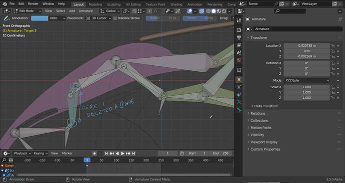
If (as is the case of the bottom right arm) you have 3 bones and want a pivot at the end “tip”, you can add an extra bone to act as a target. In the bottom right arm it is the bone named target 3.
One thing that might confuse you is that I deleted a couple of bones.
Sometimes you can delete bones in a chain that are not necessary (the ones that connect the “extra” pivot points), I did this in the hinge (plane.001) that moves the last arm.
This leaves its child bone in “parent with offset” and shows a dotted line where the bone used to be.
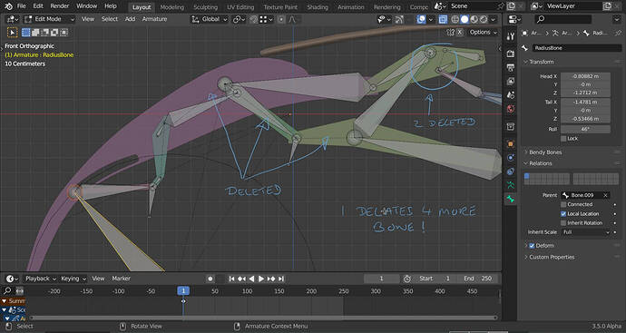
I also deleted a bone that connected bone 9 to the radius bone.
So the radius bone is a child of bone 9 with an offset.
Maybe I should have left them to not confuse you.
You can delete more bones if you want from this rig and it will still work. Here I deleted 4 more bones that are not necessary:
You could get rid of a few more but would have to change parenting a bit so I did not bother.
The radius circle is just a reference that represents the radius of the “hole in the wing” for the last support arm.
I used it to model the hole and get the center point for the radius bones root.
Anyway I was not totally satisfied with the movement of the flap in the file I sent you and being “obsessed” with IK’s decided to fix it.
The flap should first go out fairly straight and then plunge down.
So I turned the rig in space to sort of match the video perspective as best I could, then I moved things around a bit to correct the pivots and part lengths. At the end I set the rotation flat again.
Voila it worked!
Here is a new file with what I think is a much more pleasing movement and this just goes to show how important a good reference is (best an orthographic technical drawing with correct measurements.)
FlaplessBones.blend (144.0 KB)
Sorry for rambling on, I like writing things down to analyze them. I hope all this does not confuse you more! The best way to understand all this is practice.

