You’re literally changing the single Curve to fine tune this effect, what 3 values are you talking about?
I was talking about the micro roughness from thea. That one at least pretends to be physically based. Fstorm one is really just a curve. If you want that, just plug a fresnel node through ramp node into your roughness slot. But if you think you will get any more realistic or better looking results, you are wrong. Spending time on things like these will not make your work look any better in the end.
Imo the better candidate to get a correct effect, is a double coating layer approach
here’s a screenshot that shows the the double coat vs the trick
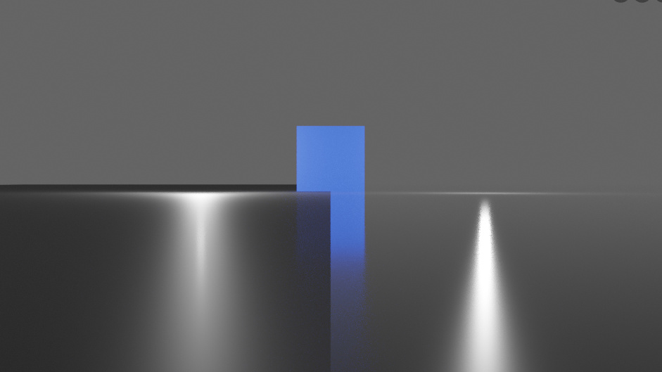
notice how using the trick totally changes the material appearance: i.e. the background blends into the material, which I don’t think it should
Yes, exactly. That effect is often consequence of material with some coat layer on top. Faking it with some fresnel falloff to drive roughness is just not a way to go.
And here’s the materials nodes:
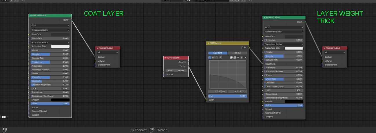
BTW, food for devs: the coat layer in principled BSDF behaves very different between Cycles and Eevee. In the latter very low values are very prominent, while in Cycles I had to boost it up to see something.
Attaching a file: just play with empty’s Y rotation
microroughness.blend (690.0 KB)
4 Likes
But sometimes it isnt. I have observed this effect on un-coated plastic surfaces, that have a very fine sub visible surface texture. This surface texture makes them dull when viewed head on, but at glancing angles, they become very glossy indeed.
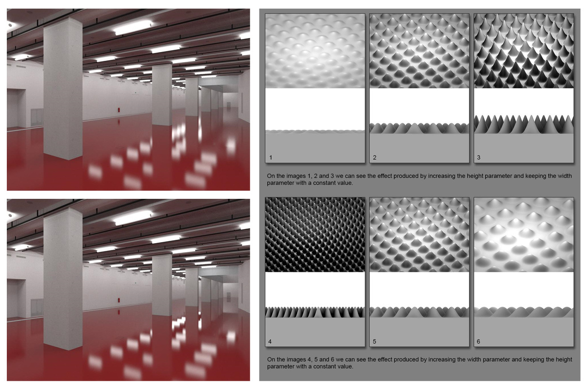
This effect seems due to the orientation of the surface microstructure, rather than any overlaying material. When viewed head on, the light can get scattered down into the valleys of the microstructure (a bit like how the pyramidal sound proofing works in sound studios) and therefore looks diffuse and dull, but when viewed at a glancing angle, the light effectively skims off the peaks of the microstructure and thus can form a sharp reflection. The transition from dull to glossy can be quite abrupt.
Part of the problem is thinking of roughness as a single value. In reality, when looking at a surface, what you are actually seeing is an average contribution from all the surface variations, orientations in the surfaces micro structure. Roughness in Cycles isn’t a true representation of a real physical attribute, but rather an approximation of the effect of the underlying microstructure of the surface. When you change your viewing angle, you are changing the relative contribution of all of these various factors and therefore are seeing a new average roughness value.
You could argue that the effective (average) surface roughness is indeed view angle dependent.
It is this change in the average surface roughness based on view angle that the node group I created in the other thread is trying to simulate.
Also my take on the shown phenomena.
Objects don’t need explicit coating to have multiple lobes. Plastics in particular all show a degree of SSS with fresnel reflection on top. When viewed head on, the (dull) SSS component is dominant, at glancing angles the sharp reflective component takes over.
Yet, roughness remains constant. It’s only the mixture of SSS and reflective components that changes.
I disagree.
Roughness as defined in cycles has no physical analogue. It’s an approximation to try and replicate a macroscopic manifestation of an underlying microscopic surface structure. Unless you know what this structure looks like, you can’t say it is constant at all viewing angles.
There is an image in another thread explaining how Thea implements angle dependent roughness and the physical rationale behind it.
This has been researched for decades, and this is what models like the GGX and Beckmann microfacet BSDFs are derived from. These models both have a roughness parameter, which by definition is view independent.
Reciprocity requires that nothing can depend on the viewing angle alone. If I were to implement photon mapping in Cycles, I would start by shooting photons into the scene. Then upon hitting a surface, I would call its BSDF to give me a reflection direction, based on parameters such as roughness. How on earth would I be able to determine a reflection direction when there is no viewing angle and thus no roughness?
i guess this is there this closure thing/limitation comes into play,like a correct reflection grating with self shadowing ect where the half vector is needed.however i think moony is on the right path.with a second map like in moonys last screenshot, you could use it as micro angle based,like a normal map for example.
edit,at this point i want ad,that on real materials with high roughness,we see the opposite effect,this means that at grazing angles with high roughness,there is more self shadowing and diffusion.so that the reflection amout falls off with increased roughness.
it depents on the micro surface and geometry that we dont have in blender.
Oh, how I wish I had a buttload of time to ingest all this above… Do we have a consensus yet on this matter?
I sometimes use things like zip-ties and duct tape… and once used a hack saw as a hammer… I just want to get the job done and make my roughness on crap look nice and realistic. Please advise.
My advice: look at a photo of the material you’re trying to match, drag the roughness slider til it looks right. Spending time tweaking curves to simulate the rounded crest of microfacets exposed by glancing angles seems like splitting hairs to me.
I have seen the photographic evidence, I do believe this is a real phenomenon, but I really don’t think it is necessary 99.99% of the time.
2 Likes
Sorry, you mistook me for a complete noob I think. Maybe I should have worded that better… The OP dude has a one-click thingy coming that will handle the initial setup with Layer Weight etc… I want to know if this is ill-advised because there is perhaps a better way that the OP was not aware of, that does things using PrBSDF settings in a more proper way, that is physically correct and doesn’t use any tomfoolery or shenanigans… Ultimately, I prefer doing things the correct way, but in a jam I’ll do whatever it takes.
Also, we call them Reference Images in the business. 
the basic setup with ior/specular reflection,should work in 99% as SterlingRoth sayed.
the OP trick is just a aproxximation that you can control by eye if you want this kind of effect.
1 Like
Cool. So it sounds like it would not be considered unorthodox or hacky to use the Angular Roughness addon when it pops out of the oven. Great!
And pixelgrip, clearly you’re a pretty smart bloke. If you simply started sentences with caps and put spaces after your periods and commas, the words of wisdom you share with others would get the treatment they deserve… Just tossin’ that out there. Thanks PG!
I didn’t mean to insult you, sorry I didn’t know the depths of your expertise. Thanks for deigning to share your vast wisdom.
1 Like
No problemmo. Hit me with a PM if you ever need tips from a pro.
Unfortunately, GGX and Beckmann are pure abstractions of what roughness is. Their statistical result is based on the presumption that roughness has a total randomness in the microfacet normal direction, and that is not a general case.
There are plenty of surfaces where roughness has some structure that doesn’t fit in a pure random normal. Nor even in an anisotropic abstraction.
And about ‘view_independency’, that’s a bit too far. Almost all of our builtin BSDFs are typically view dependent. And it’s easy to notice it as for any different incoming/outgoing ray, they produce different results (thought they are consistent in the overall mapping of both incoming and outgoing hemispheres).
Also to mention that this post is about having this effect in Eevee. Cycles works pretty good in roughness generalizations for glazing views,… Eevee doesn’t!
Hi. I also have nothing against some hacks but there are some misleading asumptions in your video who could be taken wrong.
You are describing the fresnel effect. The formula spits out 1, total reflection at high angles.
This one is good modeled in the principled.
Your two video examples could be seen as multilayer materials.
When you analyze the first wall material you get an matte paint material. Physically seen it is an base color (the orange) and an coat layer with matte paste. This matte paste generates an fine microstructure during it drys. Therefore it is not reflecting. It appears matte.
When you remove this matt paste out of! the clear coat you get an highly reflective clear coat like most car paints.
Your second stone wall example is similar.
When you polish the stone the microstrucure disappears and you get high gloss stone wall.
When you take really fine sand paper you get the semi matt apperance like in the video.
The blender principled is an nice integration of the disney principled.
See figure 16.
Only roughness, clearcoat and cleracoat gloss row. Blend out the rest.
Both real live materials in your video are dieletrics because no metals. So metallic to 0.
The first matte paint wall material can model with
albedo color (the orange) , roughness and clearcoat
and clearcoat gloss to simulate the matt paste i tried to explain before.
The integrated FO does the rest.
So here is no view dependent glossiness.
You see at glazing angles that the glossiness is cloudy because in real live you cannot paint with the same values bigger surfaces.
So a real slight big surface noise in the glosiness slot can simulate this. It s an imperfection.
The polished slightly matt stone wall behaves similar.
Another test is when you add water to both surfaces.
They get both highly gloss because microstructure is overlayed with perfect water surfaces. When it drys it gets matt again.
1 Like