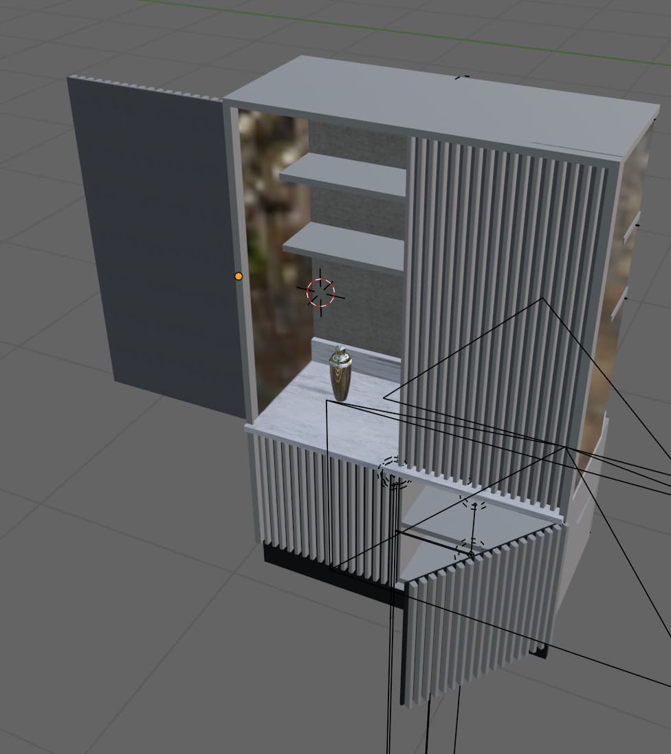
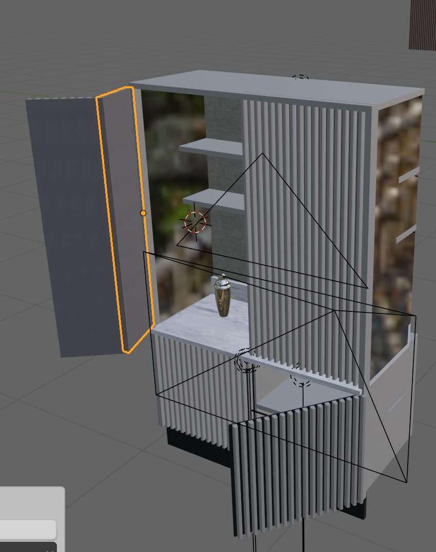
For a design project I am animating an interior scene, in which a couple of doors need to be opened.
I have used Object Constraint / Limit rotation to make the doors fold.
The opening door consists of 2 parts, which I parented to create the folding effect.
The only thing is that at the end of the animation, the doors should fold flat again (see images).
I want the door to open to 90 degrees, and the fold flat to 180 degrees, so it is open and flat to the wall.
Is there an easy way to do this?
Hope that I’m clear enough about the issue.
I am using Blender 2.93

1 Like
Those three pictures describe the behavior you want?
The second segment of the door should be parented to the first segment of the door.
When the first segment is at 0 or at 180 degrees rotation, the second segment has no rotation relative to its parent. Otherwise, it has rotation. Presumably, that rotation should blend smoothly.
That’s something where I would use a driver on the rotation of the second segment. Get the rotation of the first segment and use that to drive the rotation of the second segment, then edit the driver curve. Although something like sin(rotation) as a scripted expression would probably do what you want with a flat driver curve.
Thank you for your reply.
Yes, the pictures show what I want: opening doors to end flat.
The term driver is new to me, so I looked into it.
I will try to use that for the doors.
Thanks again for helping me out and sending in an idea of how to fix it.
Hi Bandages,
I have tried to add a driver, but don’t know how to use the curve you suggested.
Can you suggest a tutorial or something?
The driver is set, but it just opens flat with the outer part of the door.
Didn’t know that something that seems so easy is so difficult for me to do…
Thank you in advance.
It’s not necessarily easy, nothing is, don’t feel bad.
Unfortunately, I’m not in a position where I can just give you screenshots or files-- not for a few more days. And just doing some quick Googling, I don’t find a tutorial demonstrating what I’m talking about (why does everything have to be a video so you can never scan it to see if it’s talking about what you want to know?!? Arrgh!! I’m just a crusty old man who misses the days of Geocities I guess.)
I can try to put you on the right track. The beginning is to open a “driver editor” viewport, with your driven bone selected, and select the driven property in the driver editor. Open up a sidebar in the driver editor (n key for me) and switch to its “drivers” tab. On that tab, you can see what you’re using to drive, how you’re interpreting it, etc.
But most of your driver editor viewport is dominated by a big graph with a line running through it. Even though, right now, it’s a line, that’s the curve of your driver, and it sits in between your input and your output (before any scripted expression, if you’re using that.) The default is a line running through 0,0 and 1,1 so it maps any output exactly to input. But you can edit that line the same way you’d edit any other graphed curve. It’s a bezier: you can make new points on it, you can edit the position of points, you can edit the position of handles. Doing that, you can change the shape of the curve, so that it runs through, for example, 0,0 and pi,0 and, maybe, pi/2, pi/2. As you edit it, you’ll see that how the driver is interpreted changes, so if you’re driving from an angle of pi/2 (all angle measurements in the driver window are in radians), you’ll see that your output rotation is pi/2 at pi/2, but 0 at pi.
I’m sure that’s not as clear as you’d prefer, and I’m sorry I can’t do better right now, but hopefully just knowing where to start playing with things can get you started.
1 Like
Here’s a screenshot:
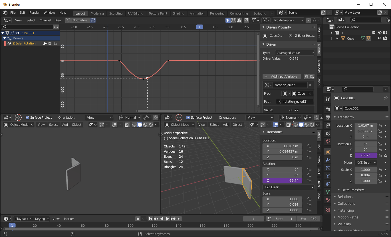
See how I edited that curve on the driver window?
On the driver window, I turned off autosnap (don’t know why this is on by default in the driver editor, maybe I need to restore factory settings though) and then created a new curve handle between the two existing curve handles by ctrl LMB on the curve (but I may use different interface settings than you.) I edited the positions of these curves (and their handles) so that when the rotation of the parent is -pi/2 or 0, the output of the driver is 0, but when the rotation of the parent is -pi/4, the driver outputs some rotation. Just eyeballed the amount of rotation. Actual values will depend on your exact needs and structure (like orientation of your axes.)
Thank you for your detailed reply.
Do you use a curve as path for the rotation?
I didn’t and could not get it to work, although I followed the steps.
It is difficult, because I have no idea what I am doing when I adjust things.
The path rotation_euler(2) I could not find though.
Maybe the path is missing? Then I could try again.
The more I try, the more I want it to work in the end.
Thank you in advance.
Hi Suzan,
to add to @bandages advice, here’s the simplest method . . .

You’ll note that in the box marked Expression it says ‘var + 0.0’.
The result of this is that Door 2 rotates the same amount as Door 1 ( var ia short for ‘variable’ and holds the actual value that Door 1 has rotated) , and as it has 0.0 added to it, it is the same value.
Since this is probably not what you want, you can then change the maths . . .

and the result is . . .
I only added a keyframe for the opening of Door 1, Door 2 was driven by that action.
Hope that’s of help,
Cheers,
Dj.
here’s the blend file . . .Door_Driver.blend (916.0 KB)
Thank you Damian,
but this is not what I intended.
I would like the door to fold a bit, then end flat with the entire door to have rotated 180 degrees.
It simulates opening a door with two segments which should end flat when it is completely open.
The fold itself I have managed to create with Object constraint.
It is the two part movement (folding and unfolding) which is causing difficulties.
But thank you for your help.
A-hah, like this ?
if so a bit of highschool trigonometry will do the trick - in the expression field use:
sin(var)*1.5
the 1.5 is arbritary, it ‘exagerates’ the degree to which the door 2 rotates before folding flat.
In the blend file I attached you’d need to change the Door1 to open to 180º.
Dj.
Yes! This is it! Thank you.
But it only works on the left door, not on the right one…
So this is why mathematics are so important;)
Thanks again.
If your geometry is identical left/right side, then the easiest solution is to copy the Left side doors, delete any keys, rotate the ‘Door1’ around the axis that would flip it correctly ( ‘Y’ in my example ) then, crucially, RESET the rotations ( CTRL-a . . . rotation ) on both new doors. Then re-key the new Door1 to the open state . . .
Best of luck with the project. ![]()
here’s my updated .blend
Door_Driver.blend (926.4 KB)
Dj.
Yes, perfect!
Thank you, this is great.
Now we can impress even more with the visualisation.
Have a good day.
1 Like