first to say thanks for developing this great Add on. It lifts the Blender and the whole workflow to a higher level. Excellent!
As an Arch Viz artist I work with floors everyday and Floor option in Archipack is really helpful.
The one thing I didn’t find in Floor editing, how to change the direction of the floor boards for example?
I know i can rotate the whole object and use Cutter, but is it possible in this way somehow:
Create Boards
Apply From Curve - so the floor sits on the curve and gets its shape
Change the angle of the boards spread. For example, I want to rotate boards 90 degrees.
Or how do you recommend this operation.
Thank you in advance and keep the great work on the Archipack
This is a known limitation in current implementation of Floor, where tiles orientation is aligned with object pivot.
So you have to create, rotate and finally cut the object.
Floor from curve does use the curve orientation as tile axis, and it is possible to rotate the curve in edit mode (select all verts) and then revert rotation in object mode.
I’m starting to implement “solid dimensions”, permanent curve based exportable/renderable dimensions, as first step to 2d export / layout ability.
The 2d representation workflow will probably use another “helper” as reference point for the 2d representation of a 3d storey, in order to layout 2d the way you want, while being able to update 2d from 3d (will try to make it as automagic as possible).
So have some questions about the way to do it:
what kind of shape for symbols for dimensions ? (arrows, cross and so on)
how do you manage your exports for printing, what kind of format, soft ?
what kind of 2d symbols may be usefull - surfaces, length, angles … ?
what kind of 2d representation for windows / doors / walls / stairs / kitchen…
level of detail for representation ?
Please feel free to share some samples of what you want to see implemented into archipack !
Also comments / suggestions are welcome.
Hello,
1st of all-thank you for so much effort and awsome results !
As to latest issues:
Id say Sketchup is quite a good reference for dimension tick marks /dot, slash, arrowss etc plus relative resizing /
As to dimensioning: to me its pretty complicated subject-good dimensioning capabilities require a lot of flexibility and ready made presets as well. V.important are capabilities of aligning dimension lines, extensions lines and dimension text, as well as formatting.
As to 2d represnt: what about section lines and their thickness/varying per construction type ?
2D layout export for detailing - Preferably dxf, no dimensions needed, because it is hard to convert them to native configurable dxf dimensions. If that is possible - dimensions included
2D layout export for presentation of idea to third party - Preferably vector pdf, with dimensions on board. A good option if nothing works is vector svg. If none of that - jpg / png
2D measuring info - distance / angle / area
Level of detail - basic 2D engineering representation of door ( 2 lines with end rectangles / arc / model number / modular size), window (3 parallel lines with end rectangles / model number / modular size), stairs (climb direction arrow / number of steps / dimensions of steps). If it is possible, maybe we could make our own 2D representation shapes that automatically adjust its dimensions and info based on the parent object.
It would be nice if we could make a dimension snapping to any two points in the scene, not having to go into edit mode or using given parametric dimensioning system. Useful for example, for distance between a chair and a wall.
Also, consider whether the dimensioning system should adjust its size to size of the screen or real world geometry.
Layout, view screen in wire mode with regular wall, windows and floor.
Layout define paper size bounds and scaling of export.
At this time only svg export is natively supported, the idea is to use inkscape as print toolbox / export to unsupported formats.
Also note that dimensions here are generated automatically by wall / doors / windows, updating on any change (user is able to enable/disable auto-dimension).
Export result of native automatic (only available for top view) symbol for walls / windows and dimensions.
Regular text and lines found into layout are exported too.
How to you flip normals on walls without going into blenders edit mode and losing the ability to adjust the paramerters of a wall. I have tried to add materials to a room wall but am finding that the material is being added to the outside of the wall rather then the inside.
as was already mentioned – architectural tick, arrow and dot/circle are most common signs. SVG export is sufficient option, as Inkscape can produce nice pdf and dxf. Do you produce the svg via freestyle rendering?
Regarding your printscreen from post #388 – dimensions should also have offset parameter to set the dimension’s distance from measured object.
When exporting to SVG it would be great to have dimensions exported to its own layer and walls to another layer to ease further work in Inkscape.
Dimensions creating in blueprint often mean a big mess – dimensions interfering with other dimensions, lines/objects etc. In such case I have to manually select the interfering/overlapping dimension text and move it slightly from its default position to better – blank/empty – drawing space. Would be nice to have some option in archipack too, so if needed, a position of a dimension text could be changed.
Regarding doors, windows, holes – dimensions should include beside a measured width also the door’s/window’s/hole’s height and its vertical distance from floor. Maybe this info could be directly taken from archipack window/door object’s, just make the dimension aware, when it is measuring the door/window/hole.
Really good job how far has archipack already gone and in such time, thx for it!
Hi Netrieb,
Svg is done through custom exporter (see layout screenshot).
2d lines are generated by archipack’s objects, and currently only work for top views.
I’m looking at generating cross-sections for other views using bmesh’s bisect_plane, as clipping / sorting edges from 3d require complex logic as found in freestyle.
Kitchen allredy require complex pre-export computation through 2d boolean as some parts may overlap (wall and ground cabinets)
Walls also require 2d booleans, window openings and walls are exported as 2 entity to allow independant filling.
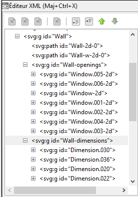
Here is current svg structure, but likely to change to allow global / per layer settings for line width and filling. Should still find an easy way to set those values with minimal user input.
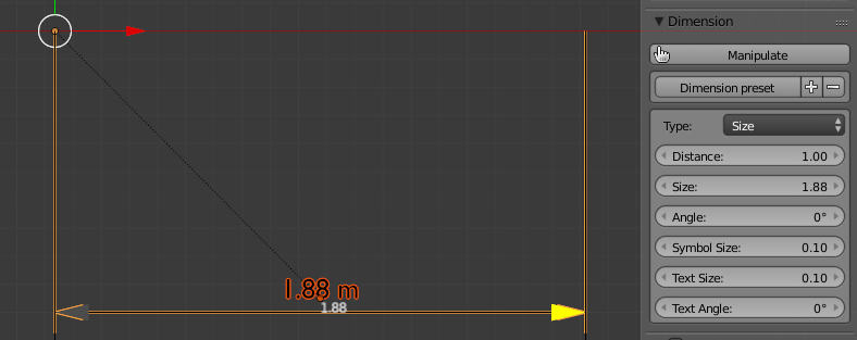
Dimension setting “distance” is the offset from mesured object.
Also dimension remains fully editable into blender, before export, the ultimate goal is to use inkscape as printer/export management tool only.
Currently there is an angle parameter for dimension text, but should probably add offset parameter too or allow direct move / scale / rotate text by user (while still update dimension in real time on edit).
Usually doors / windows opening height and altitude are in a circle in front of object, and yes it should be automatically generated from archipack’s objects size.
Also added Dimension type “Area” and “Volume” as text with small rectangle frame, “Altitude” (with oringin altitude offset)
Made size, altitude dimension support for dot, cross, tick, and arrows for inside and outside
->| |<-
|<- ->|
Still left to implement angle dimension.
@ window dimensions style:
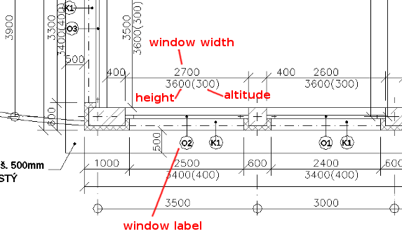
Looks like it’s varying country from country. Here in Czech Republic we have an industry standard to write a window height below a width, in the circle we just put a label of the window as a reference for reports, sum tables etc. Here is an example:
I don’t know though if this standard is used in any other country too…
@svg export:
I’m glad the freestyle is not being used, it doesn’t produce clean svg, albeit lines are geometrically correct but chopped, nonconsecutive and in a case of sections, two lines (overlapping) are created instead of just one.
@ Netrieb - Similar in our region, internal type marker (a number or a leter / number mark) inside a circle or a square together with width / height designation on the line holding the circle. The distance from the floor (altitude) is given above the line of the wall in front of the opening. The markings are missing in the circle in the attached picture.
All measures are given in cm though. This is specific for architectural documentation, other engineers usually use mm.
Quick question: How do I make a single pitch? Like the ones in photo below
All shown types Archipack roof selector, are the 2-pitch and differ in material only, the starting geometry for all is a double pitch, hipped roof.
I thought of 2 ways to do this, but not sure I got the right idea:
Start with typical double pitch and turn one side to length=0, but that produces an archipack error
Hi csimeon,
Cutter is the way to go.
Use cutter segment property to set cutted part aspect, choose “Side”, “Bottom” and “Top” according your needs, in order to generate parts like gutter, bargeboard, and half of beam for top on cut borders.
What is the different usage of slab and floor? I know that slab from wall in archipack, gives you the slab under the wall and the ceiling slab above. These are then both automatically “children” of an Autoreference Entity. I also know that ceiling slab makes another Autoreference entity and you can generate a wall on that slab. Working like this organizes work in levels.
What does the Floor command do? Isn’t the top surface of the slab a floor?
My question is above, below is a new house I am making. I had asked above how to make a single pitch roof; well, in the screen capture below you see a house (in progress) completely in Archipack. I had already tried walls, T-walls, windows, doors, slabs. This time I tried roofs, balconies, fences (balcony railing).
Nice! Thank you!