Building a shotgun in Blender, part 1.
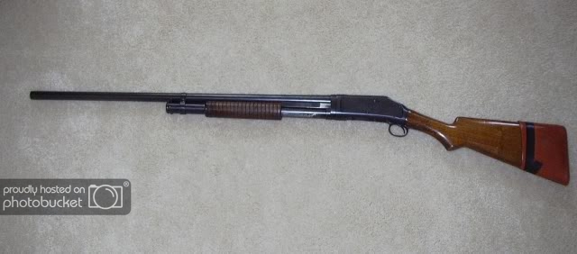
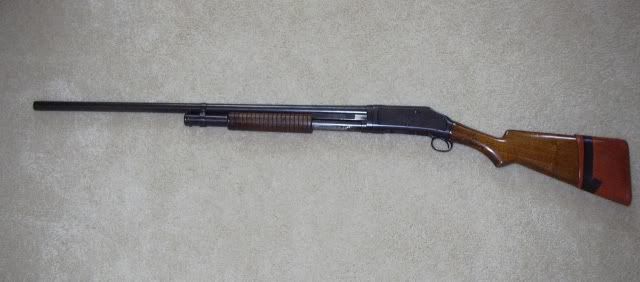
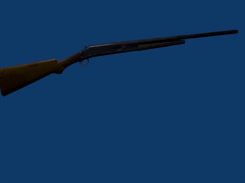
Ok, in this tutorial, I’m going to make a shotgun. Specifically, my grandfather’s Winchester Model 1897. (His isn’t actually from 1897, but from about 1917 or so.)
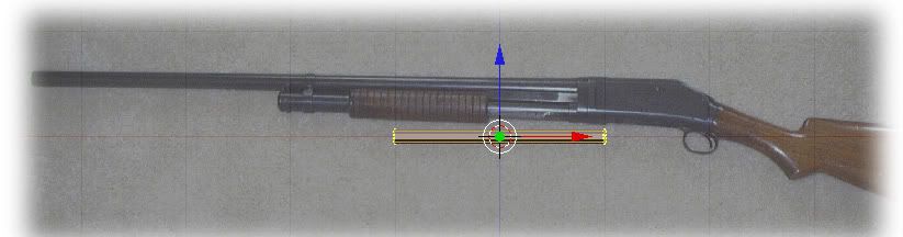
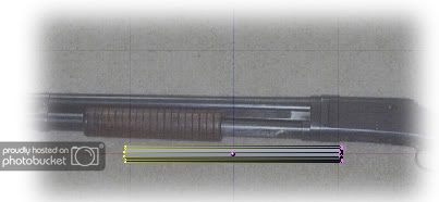
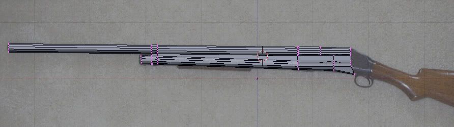
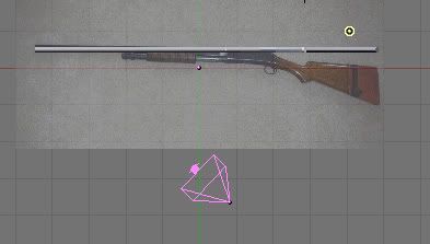
First, I’ll start with a reference pic. This is the profile.
Then, I’ll open up Blender.
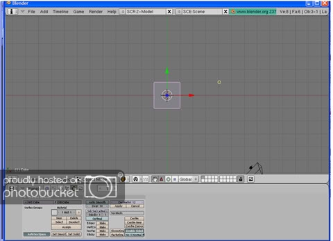
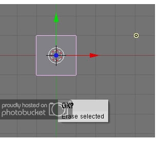
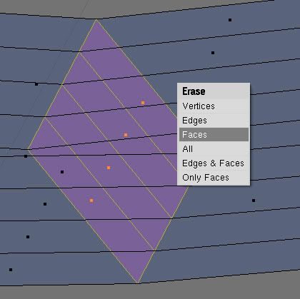
We could start with a cube, but that would be rather combersome, methinks.  So, delete that by pressing x and erase selected.
At this point, I like to hit the Num1 (number pad 1) to put it into the “front” view. This will lock in the y axis. Trust me, alot of times, it’ll be easier to adjust stuff if we’re locked into two dimensions.
Ok, now, we can either start with a tube or a cylinder. I’m choosing a cylinder. So,
Add>mesh>cylinder
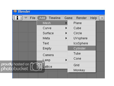
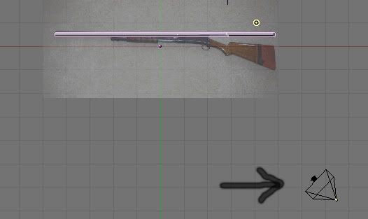
It will prompt for how many vertices, and I like 12. I think that gives a good amount of roundness without going overboard on the number of polys. At this point, let’s add the background image by going to View>background image.
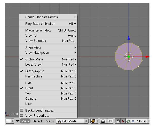
This will bring up a dialog where we can navigate to our background image.
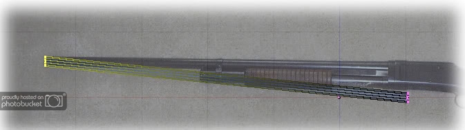
And one thing you’ll notice is that I’ve already made a miscalculation.
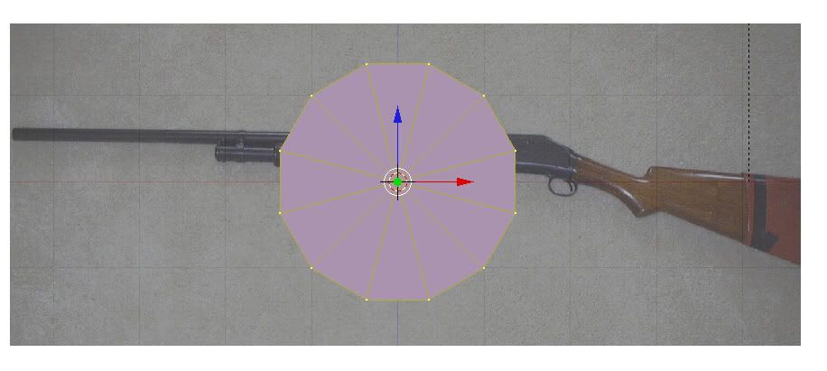
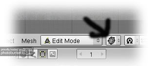
I probably should’ve locked into the Num3 Side view. Oh well, we’ll rotate the model. This is probably a good time to make sure you’re in edit mode - hit tab if you’re not, or select it in the bar in the middle. Now, hit R to rotate, then z to lock in the z axis.
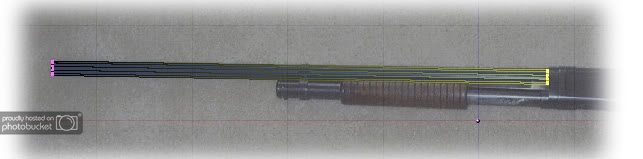
And rotate it around until it is as close to straight across as you can get it.
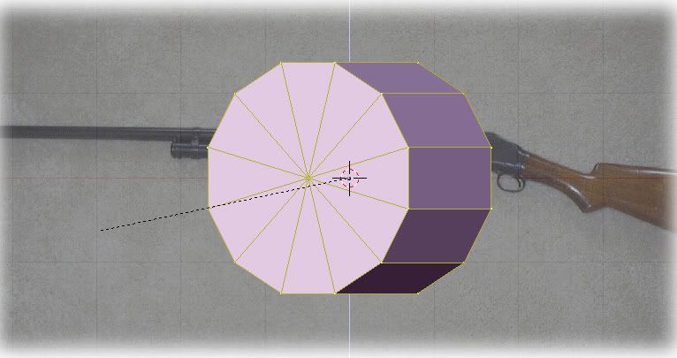
Now we’ll want to scale it down for the barrel. Hit s for scale, and make it about the right diameter. You may have to zoom in and do this a couple times.

We’ll eyeball it at this point until it gets to be about right. Then hit scale, then x to lock in the x axis and make it longer. (Oh, also hit the little hand button to turn of the annoying 3 color axis thing. And yes, I find it annoying because I don’t know how to use it.)
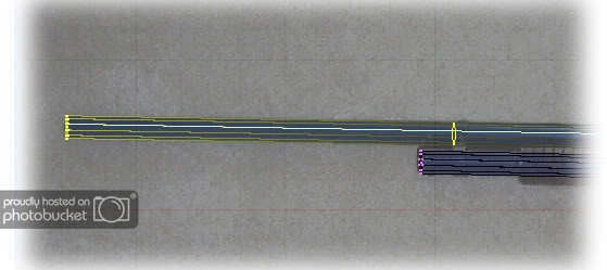
Now, at this point, we’re thinking ahead, and we know we’ll need another cylinder for the magazine tube. So, we might as well duplicate this one since its about the right size. So hit shift-D and move the “new” tube someplace for safekeeping.
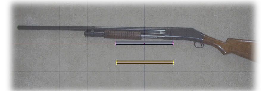
Now for starting to get things to line up! Hit A to deselect whatever might be selected at this point. Then select the left most ring of verts on our first cylinder. You can do this by hitting B then making a box around the rings, or holding down the ctrl button and lassoing the verts.
Either way, we end up with something like this.
Now, if you didn’t get all the verts, make sure you’re in wireframe mode, so you get whatever verts are visible.
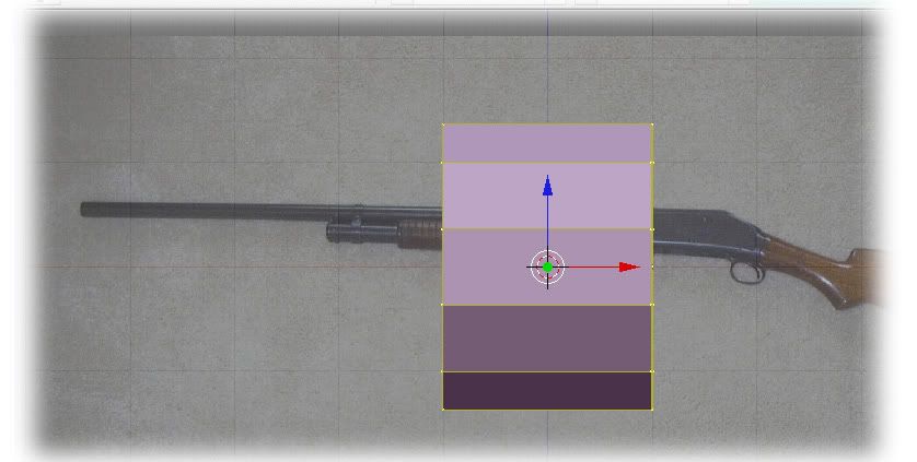
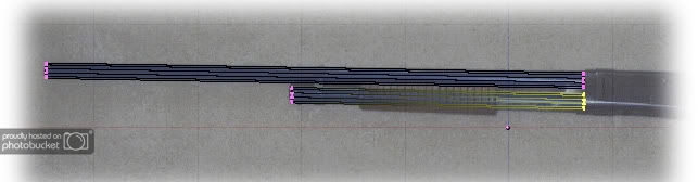
Now hit G for grab, and move all the verts from that end to the end of the barrel.
Then grab the verts of the other end and move them to where the barrel goes into the action. (Be sure to hit A to clear the selection, first.)
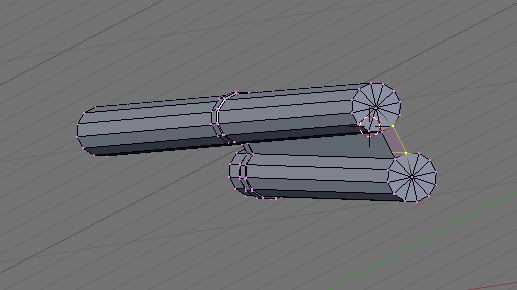
Now, we’ll do the same thing to the magazine tube. Grab one end and move it, then the other end until you have this.
Ok a break for the two most important things about dealing in Blender:
-
hit A to deselect stuff. If you’re not sure something is selected, hit A until EVERYTHING is selected, then one more time to deselect everything.
-
I haven’t told you this, but ctrl-Z is the undo. :thumbs:
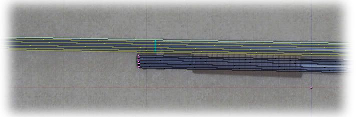
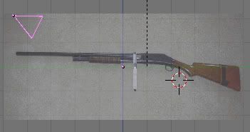
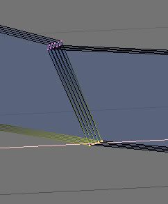
Ok, back to the shotgun. At this point, lets make sure our barrel and tube are lined up in the z axis (up and down). Hit 3 to change the view to the side.
Well, I gots good news and I gots bad news. The good news is, they are indeed still aligned vertically. The bad news is that the angle makes it look funky. Oh well, the '97 is set up so the two are angled a bit differently. So, its realistic. Go back to the 1 view. Then zoom in on the end of the magazine tube. I’m not going to worry about the tube cap. The skin can replicate that pretty well, and I think it’ll be a waste of polys. We will however, work on the bracket that joins the tube and the barrel.
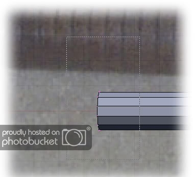
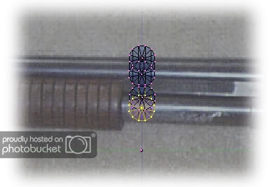
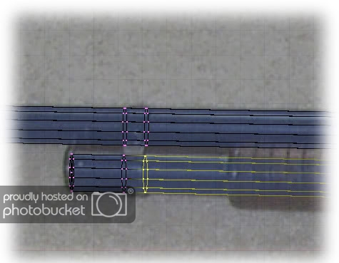
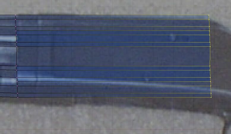
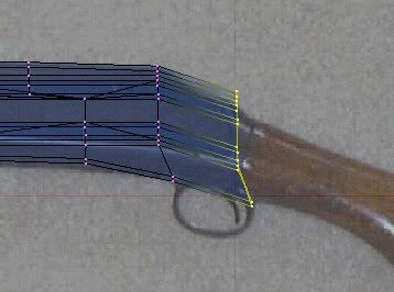
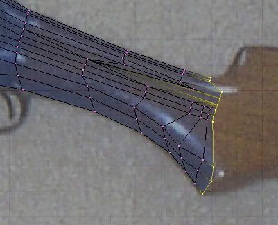
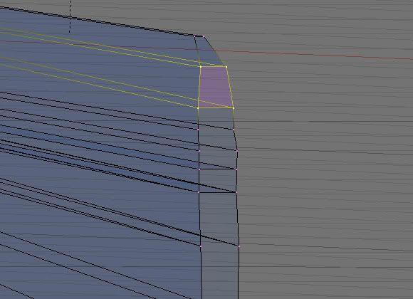
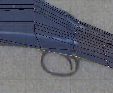
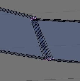
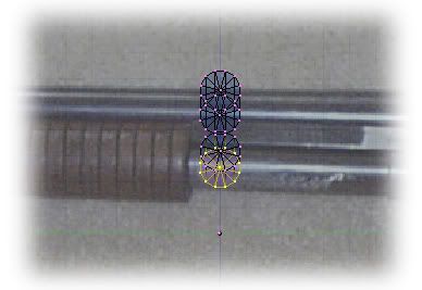
Now for one of the neatest tricks in Blender. We can add a set of verts where we want it. It is with the ctrl-R button. Its a 2 step process. First we hit ctrl-R then move the cursor over the edges until the bright yellow line is in the right plane that we want it. I find it easier to have some of the verts in the same plane already selected. (The edge it is focusing on will have a blue hilight.)
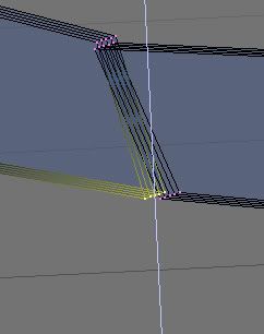
Click the left mouse button and then a bright blue set of verts will appear in the object. You can move these around until they are in the right place. We want them to line up with one edge of the bracket.
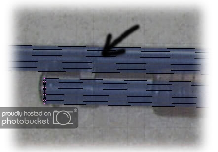
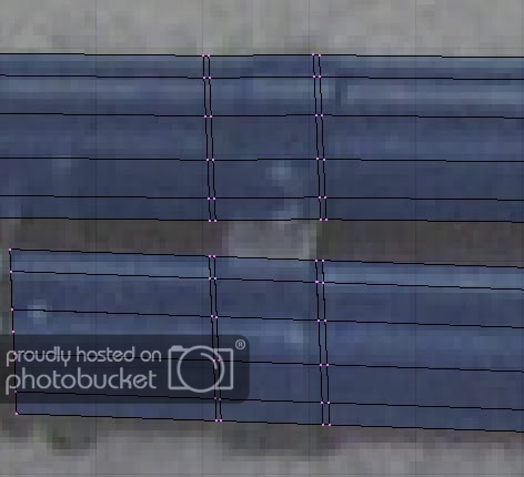
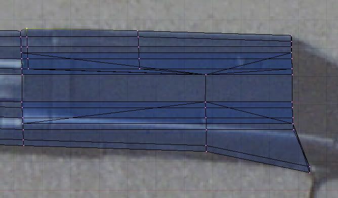
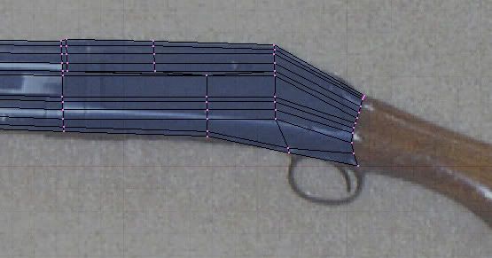
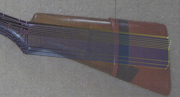
Then do this again until you have both edges of the bracket on the barrel and on the mag tube.
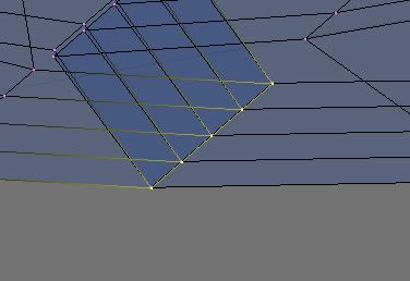
Then do this again until you have another set just outside the first set. A total of 4 lines of new verts on the barrel and tube.
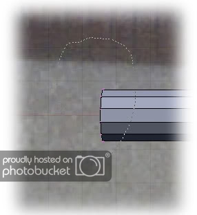
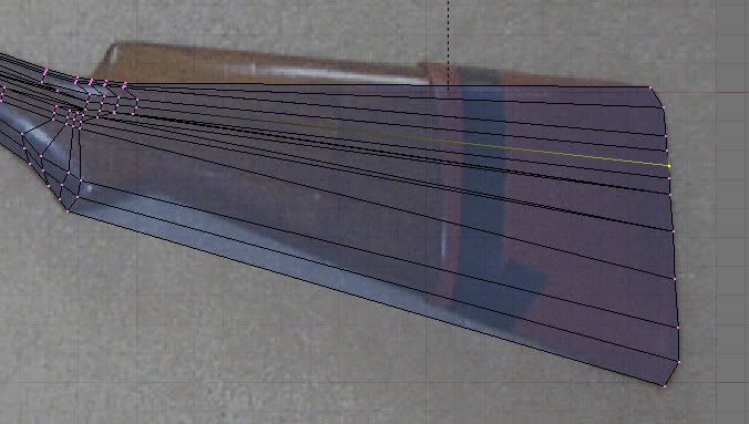
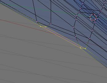
Now select the inner rows of verts. I find the lasso tool (ctrl-LMB) easiest to use for this.
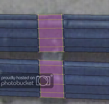
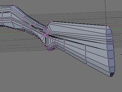
Then we scale it just a little bit so it extends up over the barrel and down under the tube a little bit.
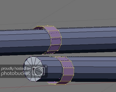
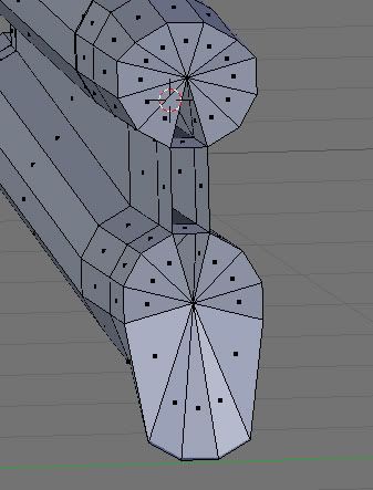
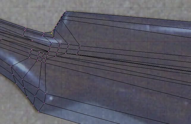
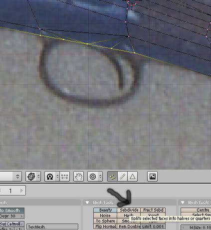
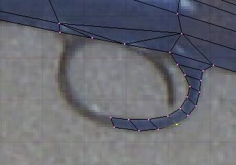
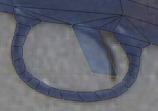
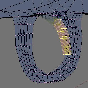
Now we need to add the tab between the to cylinders of the bracket. We do this by making new faces.
To do this, we select the 4 verts that we want to make the new face/poly. This is a bit tricky with this model because the verts we just scaled are still very close to other verts. It may take some trial and error, zooming and rotating of the view, to get the right ones. The first one should look something like this.
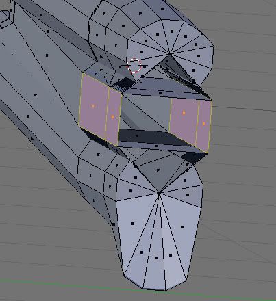
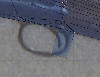
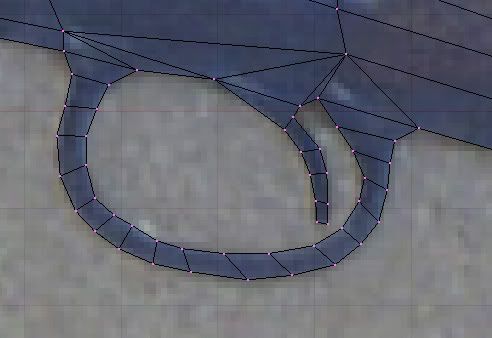
Then hit F to make the face.
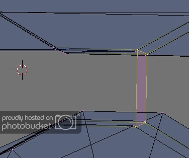
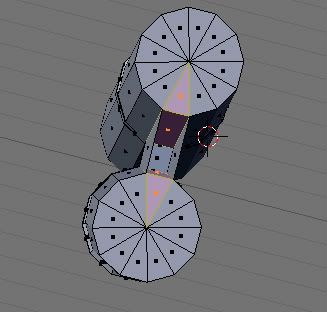
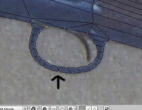
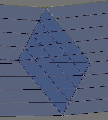
Then do that so that there are new polys going all the way around the “middle” of the bracket.
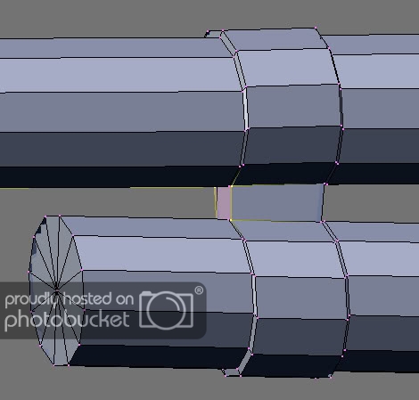
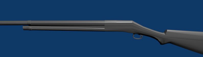
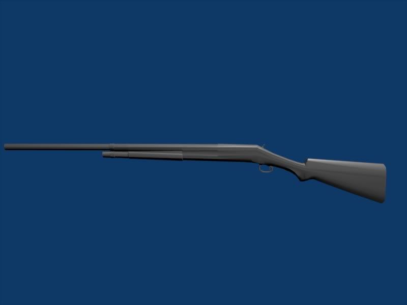
End of part I.
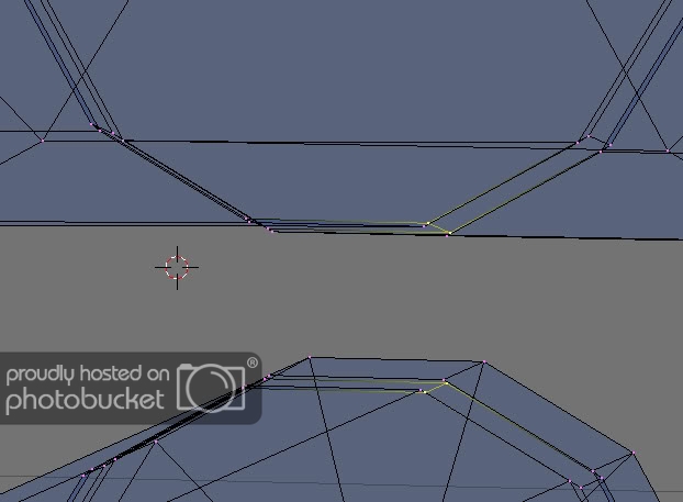
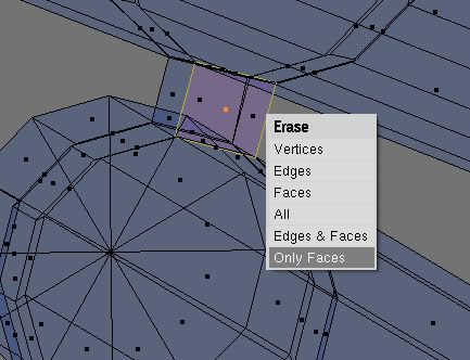
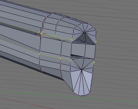
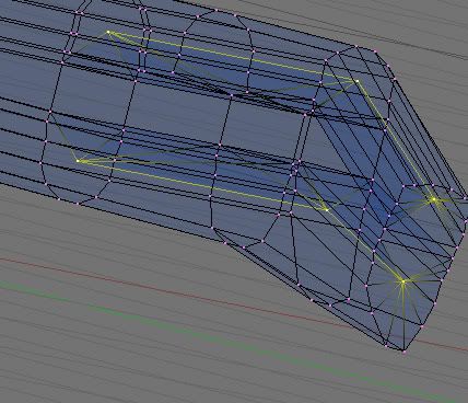
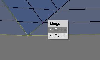
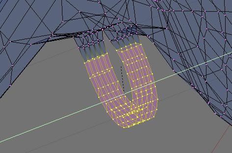
 We’re going to take out the back part of the little bracket and join the verts between the barrel and the tube. So, rotate so you’re looking down the tubes. I like face select for this kind of stuff because we’ll be deleting faces, but leaving the verts.
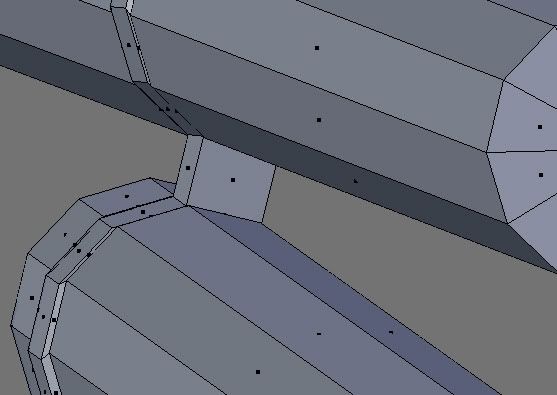
 ,
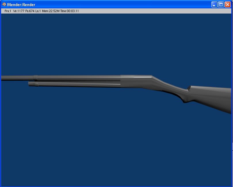
, How did you do that? Loop cut in the right places? (You also probably used alot fewer in the trigger and trigger guard, and of course, you don’t have the hammer… yeah… that’s it…)