Hi,
I’ve written a blog post sharing a Cycles tip for realistic interaction between a Principled material’s IOR and Specular value.
Hope it helps you to achieve slightly more realistic Cycles renderings.
Hi,
I’ve written a blog post sharing a Cycles tip for realistic interaction between a Principled material’s IOR and Specular value.
Hope it helps you to achieve slightly more realistic Cycles renderings.
That … is … really interesting. How did you find that out? Is that a case of “generally” or “on average” or “except in a few cases”? What about metal materials?
Thanks! I discovered the formula in this page of the Blender online manual.
I guess for metal materials it’s still a good thing to make use of the Metallic value, but it can be used in conjunction with the IOR to Specular node setup.
This blew my mind, setting my node up now!
Afaik IOR in principled node is only used for transmission, so it’s no use connecting it.
As for the specular you can arbitrarily set it to more than 1 (being 1 a soft limit), and get the same “more than real” glossy effect.
E.g. you can make a chrom-ish material by setting a dark basecolor, 3-4 specular, and roughness at will.
I use this one for some time now with good results
Yes, but it’s not a bad thing to already have the IOR input when you decide to add refraction, but I’ll emphasize it in my article for clarity.
I’ve checked the video, and yes, he refers to the same formula as I’ve used in my node setup.
Fair enough, but my node setup converts a real-life material’s IOR to the corresponding Specular value in the Principled shader, for those who want just a bit more physical accuracy.
Hmm, I can’t really agree on using IOR as input being better. Reasons:
i have to disagree,because imho the tiny subtle IOR reflection differences, between different materials,is what makes this extra realism what you are missing,if you dont use it.
like in the nodegroup vid above,the speaker is right.if you know your IOR charts,the specular value is more confusing than helpfull.
the only reason for this specular value to me is,if you use specular maps.but even for a map, we could use a math nodegroup, with the specular formular, like it is in the shader now.
look at the thinfilmshader,they material/reflection output is calculated only with IORs as inputvalues (from realworld IORs).
Thanks for sharing your points of view, @CarlG. I agree that ‘realistic’ does not necessarily equal ‘better’, that’s why I didn’t state that the formula makes things better. It just converts an IOR value to the corresponding Specular value in the Cycles Principled shader, for those who like to go the physical way, following this quote from the Blender manual: “To compute this value for a realistic material with a known index of refraction, you may use this special case of the Fresnel formula: specular=((ior−1)/(ior+1))2/0.08”
Regards,
Metin
Nobody would notice. I’m guessing not even you. You would know, and it bothers you, but nobody would notice these subtle differences.
In my work, I use it to bring down reflections in i.e. cracks between wooden planks if I don’t want to mess with the roughness (which is actually what you should do). Or let AO maps drive it (will get more important with Eevee). Or, in some cases, I will tweak it a little for tuning the output. It’s user friendly and can be audited with ease, whereas values > 1 cannot. Remember, this is a Principled shader, not a Physical shader - from Disney:
Frankly, I don’t even know why Blender has a different ClearCoat nomenclature (using roughness at full range instead of gloss at reduced range), as part of the idea was to have maps being transferable between systems. Now it is completely broken anyway (works in Eevee, but not in Cycles), so I use my own topcoat.
Conclusion note from Disney (which I agree on, from the bidirectional paper):
Rendering is now a sampling problem, as shading and lighting are physically based. But this does not mean
that everything must become photorealistic and absolutely physically correct. The goal is still to render
visually pleasing images, so being physically based should not prevent artistic creativity.
Interesting. So if I’m correct you’re saying Roughness should be a constant value, and differences in reflectivity should be controlled by using a map in the Specular slot? Could you shed some light on that?
No. You should drive everything with roughness and let specular be constant.
But in some cases it makes life easier to let the roughness map do its thing and reduce reflectivity in cracks (in my case) using specular. Roughness map may be in the 0.2-0.8 range (and I don’t know where), if I added 0.5 to roughness in cracks I might end up loosing definition (or I’d have to do a lot of math nodes to compensate). Since spec is 0.5 and not driven, I can just reduce it slightly in the cracks using 0.1 instead. It’s 0.5 since that covers “all” dielectrics, but you can use it for artistic freedom like this.
And yeah, I know - wood should have the same spec topface and between boards since its the same material, but in real life those are proper boards as well, with actual geometric depth, not faked as a simple plane.
Edit - a couple of tests.
Here is what it would look like using Principled on the wooden floor, specular locked to 0.5 (=IOR 1.5 ~ “all” dielectrics), also using the buggy topcoat (which don’t have thickness control, only fresnel):
This is Principled on floor again, but I’m reducing specular for the “gap” between the boards. I also have my own topcoat with thickness (varies with glazing angle, kinda weirdly, but I’m not sure what the proper way is):
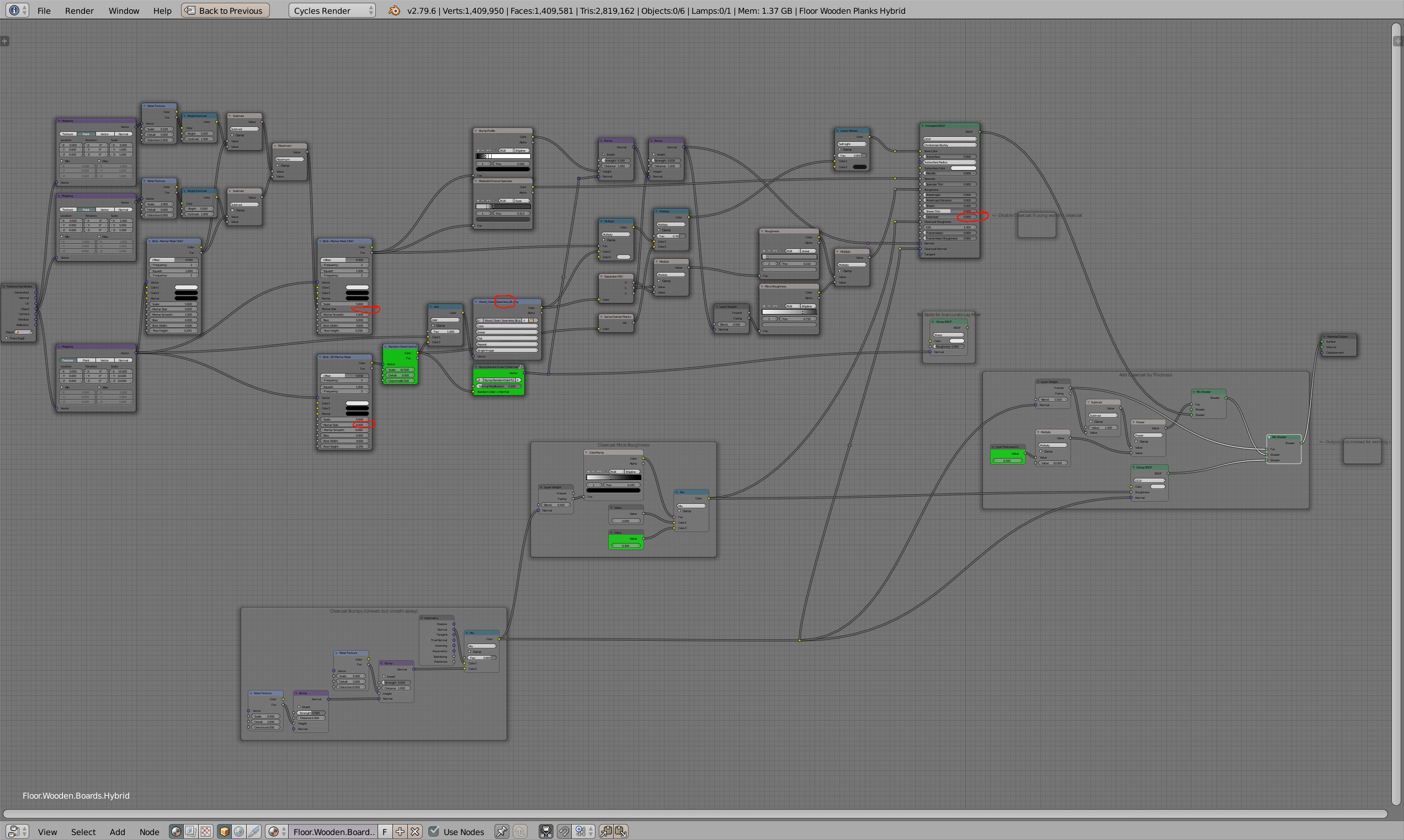
The nodes for the floor. Using brick texture for various means - controlling plank gap with to not look ultra perfect, gap profile, random texture location lookup and some random darkening - it’s a big seamless texture, but good look finding obvious/instant repeats:
Oh, btw. Lucy and Suzannes has 3 sharp areas of different IORs (1.46 plastic, 1.54 ivory, and 1.635 asphalt). As a sharp transition, should be easy to spot, right? ![]()
yes i agree too,but i think you are mixing things up here.
i correct it for you
the formular under the hood,(like in the vid) calc the specular value back to a fresnel value.the shader still uses the fresnel equation.that is the important point.
and here is the point there i think you are mix it up.
in short.the principled shader is lacking a costum/preset fallof control of roughness and fresnel.
what you are described is to try to compensate the grazing edges with roughness.
but a structral rough material in real would have less reflection at grazing angles,it gets more diffuse the more rough it gets.
and i agree that the missing fallof control makes it sometimes difficult with material that is rough and should look rough ,especialy at the grazing angles.
Ehhm, no. Or, maybe badly described. Basically, in this case I’m trying to create a fake shadow in the crack between the planks in order to give the impression of depth. See reflection occlusion at the bottom of this page. Such a (usually AO, but I’m driving it directly) map is already in the 0-1 range. Almost ready to be plugged into the specular input. Unless I knew the formula above, I wouldn’t know how to translate it. But division by 2 is something everyone can understand, even artists ![]() Also note that the layer weight/fresnel 0-1 way is probably there for a reason.
Also note that the layer weight/fresnel 0-1 way is probably there for a reason.
But yes, generally speaking, if you want something less reflective in a PBR way (for a material with a given IOR), you increase the roughness. But sometimes, if you don’t want to mess with the roughness for fear of loosing control with it or whatever, it is very convenient to have the specular control available in a way that accept easy to handle 0-1 range.
Hmm, polarized dielectrics (photo water/people with and without polarizer to reduce reflections); would you manipulate f-0, fresnel shape, or simply lower the total output? I know, side tracking, but…
Example image from the real world here.
interesting tech methods.but i think this goes oftopic.maybe you want to open a new thread about this.
polarizer filter out the electric magentic lightwaves.for example horizontal or vertical mostly used for image processing.you can rotate the filter too.the filter has atomics layed out in one direction simple sayed.
you could simulate that,if you build a fresnel equation and use the s pol and horizontal p pol calculation seperatly for output.
Magnetic lightwaves? Horizontal, vertical? Processing? Atomics? S Pol and P Pol? Fresnel equation?
As an artist, wouldn’t I just reduce the specular? 
Sorry, it was a trick, couldn’t resist. And btw, that trick don’t work with principled based water as its specular is tied to the transmission IOR (as it should be).
yes in theory it is just this,kind of.depents on the filter direction.
but i think only seperate the fresnel into 2 pols are not enough to filter out a render.it should filter out the rays like in real.
here a interesting read about rendering polarization

