While there are obvious limitations, it seems to be up there with mObject.
Your Motion integration would be super helpful for TV station bumpers and idents, also sports program packaging (team logo insertion and player position animations).
While there are obvious limitations, it seems to be up there with mObject.
Your Motion integration would be super helpful for TV station bumpers and idents, also sports program packaging (team logo insertion and player position animations).
Wow! Great shares! Thank you. It is amazing how fast Blender is moving! 
mObject is a whole other beast as we can play with the 3D object from inside Motion. MotionFX did an amazing job at that. But for those that want to take advantage of Blender with all of its features then this script is a perfect combo.
Hello! Just wanted to share the tutorial on how to export Blender to Motion has been published on Blender Nation! Woo Hoo!
That’s great, I have been making some progress on the Euler filter and making a couple of other improvements. The filter is trickier than I thought it would be and I don’t know if it’s completely right yet. The problem comes from Euler transforms hitting a gimbal lock and flipping the axes. Blender internally deals with Quaternions but the translation back to Euler rotations causes the axis flipping.
You can actually simulate the problem directly in Motion, I’m not sure why they allow you to set rotations that way. To see the problem, open a blank scene in Motion, add a camera and add either a rectangle shape or just drop an image in and then switch the camera to perspective and move it around a bit to see the object. Select either the object or the group and go into properties and open the rotation tab. Set x to 90 and drag left/right over both y and z and you can see those two separate rotations move the shape in the same axis. So you can no longer rotate the shape sideways using the properties. That’s basically what causes the axis flipping - you lose a degree of freedom because the rotations are calculated in a particular order and when one axis hits 90 or 270, it locks the other two to the same axis.
Blender doesn’t get into this problem even when interacting with Euler rotations directly because it always uses global rotations around the local anchor point to set the rotation.
The effect this has when translating from one app to the other is that it creates large discontinuities or breaks in the rotation curves. This doesn’t affect the position of objects but it affects motion blur sampling because it samples between frames. I have an image example here:
The curve at the bottom left has broken apart and when the motion blur is enabled (I increased the motion blur angle to show the effect more), it is sampling frames with extreme rotation and if you look at the left image, the grid lines criss-cross and the transparency is wrong whereas on the right, the grid lines and transparency are consistent as the rotation curve no longer has the discontinuity. This shows up as a flicker during an animation when motion blur is enabled.
There are multiple different artifacts that show up though. The one above is the easiest to correct as it’s just a single axis flipping 360 degrees out. There are at least another two. One is where all 3 axes flip +/-180 and another where just two axes flip +/-90. I have corrected the 360 flips and the 180 flips but I haven’t figured out how to correct the 90 degree flips. They don’t seem to introduce motion blur artifacts that I can see and I couldn’t correct them manually. If I flip them back round, the animation goes in the wrong direction. Here’s a more extreme test where I have the camera rotating all sorts of directions:
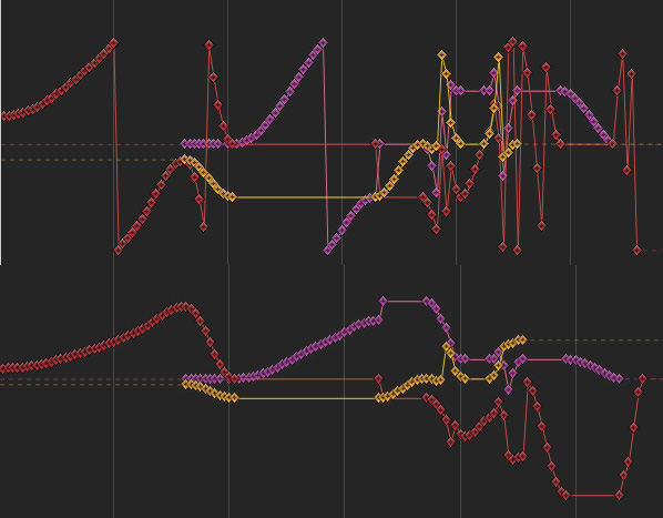
The curve below is the corrected one and is much smoother. You can see the 90 degree flip just after the 3rd vertical line where the red and purple axes jump in opposite directions. Like I say, if I flip those back around, the yellow axis rotates the wrong way. It works ok if I correct it backwards but this would probably affect rotations before it. The most important thing to make sure of is that the scene moves the same and everything still points the right way after the correction so I’m still checking that this is the case.
I have also fixed the camera to output the render camera at the top so that it defaults to the active camera in Motion. For some reason the currentframe being set to 1 set the frame to 2 when the scene was opened in Motion so I set it to 0 and now it opens as frame 1.
The script is formatted now in a way to be bundled with Blender but I want to add a couple of other things to it before I submit it.
I have a test script here:
http://www.dev-art.co.uk/files/motion_camera_tracking_150729.zip
Try it out on some scenes to see if all the rotations are still ok. You can disable the filter by setting the do_filter variable to 0 or 1 and reloading the script to see the difference.
Wow. Very impressive Andrew! I will have to test that right away. I am in middle of one project and as soon as I am done I will see what we can create using this new script. Should we do a very complex rotation animation to see if it can handle it?
Thank you for your hard work good sir!
I did another more in-depth rotation test comparing motion blur directions and whether the rotations were consistent and it showed an orientation going the wrong way because of the way the 180 flips are done and these still cause differences in the motion blur vs the original animation so I’ll need to figure out another way to correct those. Sometimes one axis flips 180 but the other axes don’t change direction, nor do they change more than 90 degrees so an algorithm that checks the curves separately isn’t going to work properly. I’ll have to check for a large discontinuity in any axis and then adjust the others accordingly and then correct any remaining 360 flips.
I wonder if C4D was able to handle this challenge?
It doesn’t look like it by itself. They have a feature to save a compositing file, which bakes out the rotation data. On my complex test, the result going from Cinema 4D to After Effects is the same:
Notice all the breaks and axis flips. They’re supposed to look something like this:
One interesting thing though is that in order to actually do this test in the first place in Cinema 4D, I had to change the object rotation method from HPB to Euler XYZ. HPB is supposedly a way to avoid gimbal lock but it also has the effect of removing a degree of freedom in the interface (like Motion) so you can’t actually do certain animations in the first place. If you make a plane in Cinema 4D, click the plane and set the values in the coords tab, set P to 90 then H and B do the same rotation so you lose a degree of freedom. In order to rotate sideways, you’d have no choice but to add a parent object and rotate that instead.
Cinema 4D and Maya have Euler filters to correct curves for imported data but I can’t see what they do. In Cinema 4D, they have a function called GetOptimalAngle, which requests the rotation order and corrects an input angle:
This might however have some unwanted side-effects on large rotations. Some scripts try to constrain adjacent frames to be within 180 degrees of each other but this would break curves that legitimately have larger differences because they don’t know what the intended rotation was.
Correcting the 360 breaks goes a long way towards cleaning things up and that doesn’t have any side-effects so that’s ok. For other artifacts, I’ll try and identify them individually but some of them can’t be corrected because there simply isn’t another orientation that maintains the animation direction.
If you have one axis sitting at 90 degrees, you only get one other axis option so the only way to rotate the other way is to flip two axes 90 degrees in one go and this creates the wrong motion blur.
I originally thought Blender was able to avoid the axis flipping in the UI but it seems to not be the case either. If you look at the following image, these are 3 frames one after the other:
You can see the middle plane flips 180 and back but the angles in green aren’t 180. What’s happened is that by setting Y to 270, X and Z now share the same axis so it adds 73.445 to 106.087 = roughly 180 and 144.6+208.9 is close to 360 so it flips back.
It’s just the nature of local rotations unfortunately. The only real way to avoid this is to use Quaternion rotations or some other rotation scheme that avoids gimbal lock by using a 4th axis. None of the others are very intuitive to use when animating though.
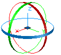
I think the axis angle option, which is a choice in Blender is the most intuitive, however I don’t think the way it’s set is intuitive. The axis should really be set automatically and the user adjusts the 3 rotations. For example:
This would always be intuitive because the user is always aware of the axis being rotated around at any given point and this axis always has all 3 axes point in different directions. When animating, the system would need to store the vector at every keyframe and the rotation used to reach it.
f1 would be 0,0,1
if the user rotated 720 around x, the rotation boxes would be left active to allow setting the keyframe, if it is set,
f2 would be 0,0,1 x=720
This way it knows to get from f1 to f2, there was an x rotation of 720 in between but the vector ends up pointing the same way.
This still wouldn’t help apps like AE or Motion unless they switched to using the same system though.
Another idea for rotations would be using a global axis for two of the rotations and local for spin. So the rotation is contained in a sphere, which has a direction that is fixed globally. To reach any point on the surface, always rotate round the global vertical with an angle and then the other angle is an elevation. Lastly you have the spin around this vector and the spin would show in the UI where the local axes were and there would be snapping tools to align the global rotation values to the local axes.
This could never get stuck because you would always be evaluating two global values from the same fixed axis and a spin that doesn’t conflict with them and none of them would remove a degree of freedom.
Say we start with the standard global axis with a plane flat and the spin axis is up. If you rotate around x by 90, this would be stored as (90,0) with spin 0. Locally, the y-axis would now be pointing up. To rotate around y by 90, we don’t store this new location as (90,90,0), we store it relative to the global co-ordinate system where we are back to zero so this gets stored as (0,0) with spin 0.
To interpolate between the first two in an animation, it would by default assume a linear path across the surface of the sphere but the user could tell it to go the long way round and multiple revolutions can be chosen and the animation curve would determine slowing down or speeding up.
Using global axes makes it harder to do certain kinds of movements because if the object has a spin on it (local z-axis) and was rotated at an angle, how could you for example make it oscillate around its local x-axis when you can only keyframe against the global x and y? Well, it already knows where the local x-axis is in this global system from the spin angle so it can do this no problem in the UI but the keyframes would be stored against global x,y.
No gimbal lock, intuitive to set rotations and animations that make sense because it’s still just 3 rotation values.
I highly doubt Motion would change their code in order for it to work with Blender. Especially with some many 3rd party tools tied into it.
When you mentioned the Sphere, would we use Spheres instead of null objects so we can share more rotation info or would it be dependent on the type of animation we are trying to achieve?
Unfortunately I doubt any app, even Blender will move to a new rotation scheme but the existing options all have problems.
The sphere I mentioned is just a way of imagining how the rotations would work. All rotations happen in a virtual sphere.
The Euler way is to rotate in X, Y or Z in a sequence but you can see in that image, if you rotate one by 90, it aligns with another axis so you lose a degree of freedom. Euler angles should really be scrapped entirely because they are too problematic for 3D animation.
Quaternions rotate around an arbitrary axis so you have to think of a line pointing from the middle of the sphere out. (0,0,1) would point up. Then moving the angle rotates around this line, which for 0,0,1 is Z. This doesn’t lock but it’s not intuitive to know where to set the vector, which makes it impossible to use for complex animations. It also behaves oddly like the angle doesn’t keep rotating the higher up it is set.
The best scheme should be intuitive and avoid gimbal lock. Rather than using a vector like Quaternions, this part could be replaced by two angles (rotation, elevation), which are set relative to the global axis, not local like Euler. The last angle spin would be set relative to the local up-axis and would rotate around it like the Quaternion angle does. These angles could go as high as necessary for multiple rotations.
If you wanted to spin an object sideways for example, you’d set rotation to 45, spin to 0 and then animate the elevation as many revolutions as necessary. These axes can still align at times but they don’t lock each other because the global rotation and elevation aren’t affected by the local spin angle.
This also gives you the benefit of being able to animate like Euler because the local up-axis is always known so the interface can let you set global rotation and elevation values that match local x and y.
Anyway, that doesn’t help the current situation and would take years to get implemented. The good news is that I have managed to sort most of the discontinuity. I had to run 3 separate filters, which required rewriting a lot of things. In order to save memory during export, I clean up keyframes as I go but to do the filter, I need to see all the keyframes so I tried to do it during the export before duplicates are removed but multiple filters conflict with each other so you can’t run them on each keyframe.
This meant I had to iterate over the objects later on and fill the keyframes back in, run the filters sequentially 3 times and then remove the redundant keyframes again. This slows things down a little. I tested performance exporting 2000 frames with 1000 objects and the export time was about 5.5 minutes. I felt this was a bit slow and narrowed the bottleneck down to the dictionary object storing the data. It does an allocation for each of 9 curves so 9 x 1000 x 2000 = 18 million allocations.
So, I thought I’d try storing the data in a different order so that it set all 9 curves at once, which would be 9 times faster (I thought). I spent all day yesterday rewriting it with the new data order and it only saved about 20-25% because it added overhead in other parts of the script and it turns out that 1 allocation isn’t 9x faster than 9 allocations for some reason. So I just scrapped the new scheme. I have a couple of ideas on how to optimize the performance but today I’ll add some UI features to adjust export options.
Once the UI is in place and I have tried some other performance optimizations, the script will be ready to go and it can be bundled with Blender.
You have really dived deep into this script. Thank you for all the hard work.
I doubt many of us will ever get up to 1000 objects but I can see you are trying to stress test it. I look forward to see the UI you created. Please let me know when you have something that is ready to test.
Also, when you have some open time, I have an idea for another project and I think you would be the best person to talk to about. Which is the best way to contact you directly? PM, Email or other.
Thank you again Andrew for all your amazing and brilliant work. You rock good sir!
The UI parts are just some options to adjust the output so nothing much special. You probably won’t even need to use it but if the curves ever came out wrong it saves going into the script to edit the text.
PM is good, I get notifications by email.
Ok got it. Do you think your suggestion of having Motion switch to the same system would make Motion Better? The reason I ask is that I have a feeling that Motion will be adding more 3D tools. Maybe this is something we can bring up to them now if it helps make their software better?
I will PM you now.
PM Sent.
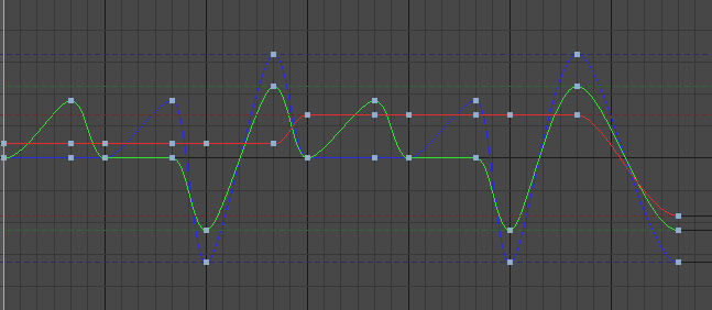
I think it would make Motion better for the reason it avoids that condition where you lose a degree of freedom while rotating objects. When moving from one app to another there would be zero axis flips and the motion blur should be almost exactly the same. More and more 3D is being integrated into motion graphics and the axis flips are annoying to have to deal with. Composite transforms try to constrain rotations to -180, 180 so in the following image, Blender’s curve looks like the top part and unfiltered, the output is in the middle. The rotation positions are fine but the object is actually oscillating back and forward so the motion blur on the object would be unusable. The filter that I added now looks like the last image, which matches Blender. It won’t always match this closely though.
I uploaded the test script here:
http://www.dev-art.co.uk/files/motion_camera_tracking_150806.zip
The UI is stored in two places. If you hit the n-key in the 3D view, there is a settings panel for each object. This panel allows you to turn off parts of the Euler filter if the curves don’t come out right. It also allows you to set objects as dropzones and it will automatically output dropzones and dropzone transforms above them so you don’t have to do this manually.
The other setting is in the properties panel under the scene tab. It’s just an option to set the rounding accuracy. By default it’s 4 decimals, which should be fine for removing redundant keyframes while matching the render.
The overall performance isn’t too bad. I set the script to ignore static objects when doing the Euler filter so that improves export for heavier scenes. 1000 objects over 2000 frames is just over 3 minutes. I added an export progress in the console so that people are aware of what stage the export is at. I’m not sure if Blender has a progress bar in the UI but that would be nice like a dialog that pops up preventing people interacting with the scene during export but showing a progress bar with a cancel button that kills currently running scripts.
I’ll check how to submit this as an addon for Blender and it can possibly get bundled to save people installing it manually.
Small update, something must have broken the layer check along the way. This is used to hide objects from export - you put objects on a hidden layer. I use a different method for checking objects in active layers now and I improved one of the filters.
http://www.dev-art.co.uk/files/motion_camera_tracking.py.zip
I submitted the script for inclusion with Blender so maybe it will get included in a future release.
Thank you Andrew! I am have not had a chance to test the script yet. My store is being updated and it is taking longer than I had thought. As soon as it is done I will jump to test the new script. I am sure it work perfectly.
Hello Andrew and good day.
I love the drop zone feature. It saves time. The only bug seems to be that if we use more than one Drop Zone they show up empty in Motion. We just need to reconnect them, but I just thought you would want to know.
Also, I created a quick animation to test my limitations. I did box with a rotate of -180 degrees with 4 drop zones attached to 4 faces.
Inside of motion at frame 60 it flips the entire animation over. Please let me know what I did wrong. Below I attached the blender file along with the motion file for you to look at. Thank you again for all your great work and have an amazing day!
Here is a video explaining the flip: http://quick.as/0lwtrOQq
Thanks for testing that, those issues were down to a couple of bugs. The flip was because when it filters out duplicate keyframes, it uses the default rotation if there isn’t a previous keyframe but the angles are written out in radians and I changed it to work in degrees to help with the Euler filter so it was using a radian value for the first keyframe instead of degrees. The drop zone issue was because of a duplicate id. Every object gets its own id but the media layer comes at the end and so it uses static id numbers and I’d set one of the layers in a way that conflicted with the other object ids if there were enough objects in the scene so it’s now set out of the range. The updated script is here:
http://www.dev-art.co.uk/files/motion_camera_tracking.py.zip
The drop zones all face the same way as the nulls all face the same way. To get those looking right in Blender, if you switch the transform dropdown in Blender to Local for the axes, the up direction for the drop zone is in negative Y, basically the opposite direction to the green arrow.