if you try to follow the cross sections from blueprint to get a 3D curve
it is difficult to get a smooth 3D curve!
so is there another trick to get some smooth 3D curve for the back and front of boats or planes ?
thanks
happy bl
if you try to follow the cross sections from blueprint to get a 3D curve
it is difficult to get a smooth 3D curve!
so is there another trick to get some smooth 3D curve for the back and front of boats or planes ?
thanks
happy bl
@Ricky
Cross sections?
Oh, recollecting one of my first 3d projects, many years ago.
I suggest to avoid curves. Do it by a nice subdivided line. Just modify the subd line on any cross section blue print.
Bridge loops. (loop tools addon helps a bit, “space” plays well)
It’s a matter of nice topology.
I didn’t find curves very practical on boats, I may be wrong.
Curves should actually be the proper tools for boats, (the word ‘Spline’ comes just from the name of wooden masks used for building boats).
Curves in blender are a sort of tricky though, I can suggest to make use of less points as possible, so to get smooth shapes, and the same for sections, the less the better.
paolo
let me try to re explain that
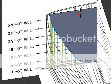
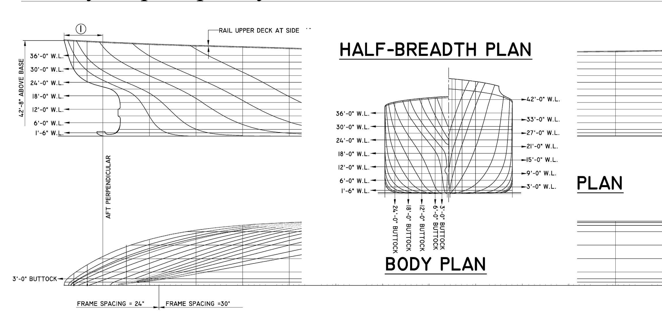
here is pic showing the cross sections in top and front view - blueprint
on this blueprint you have the different curves for cross sections
form which you can make the 3D hull shape
now different way to build this 3D hull surface
1- nurbs surface - skinning
which gives geometric continuity and is best way I guess
but more difficult cause limited to quad and not easy if there are sharp corners!
and hard to follow very in small areas with quads too!
2 - use mesh verts and adjust each point one by one
which is probably easier cause not limited to quad
b<b>ut very difficult to get smooth 3D surface </b>
also if u look at pic numbers of front cross sections is not the same then on the top!
so have to find which one goes with the other !
hope you get the idea here
thanks for feedback
happy bl
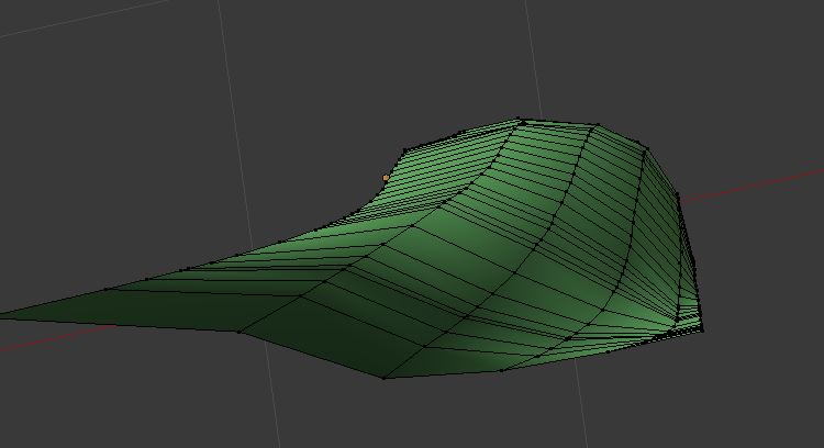
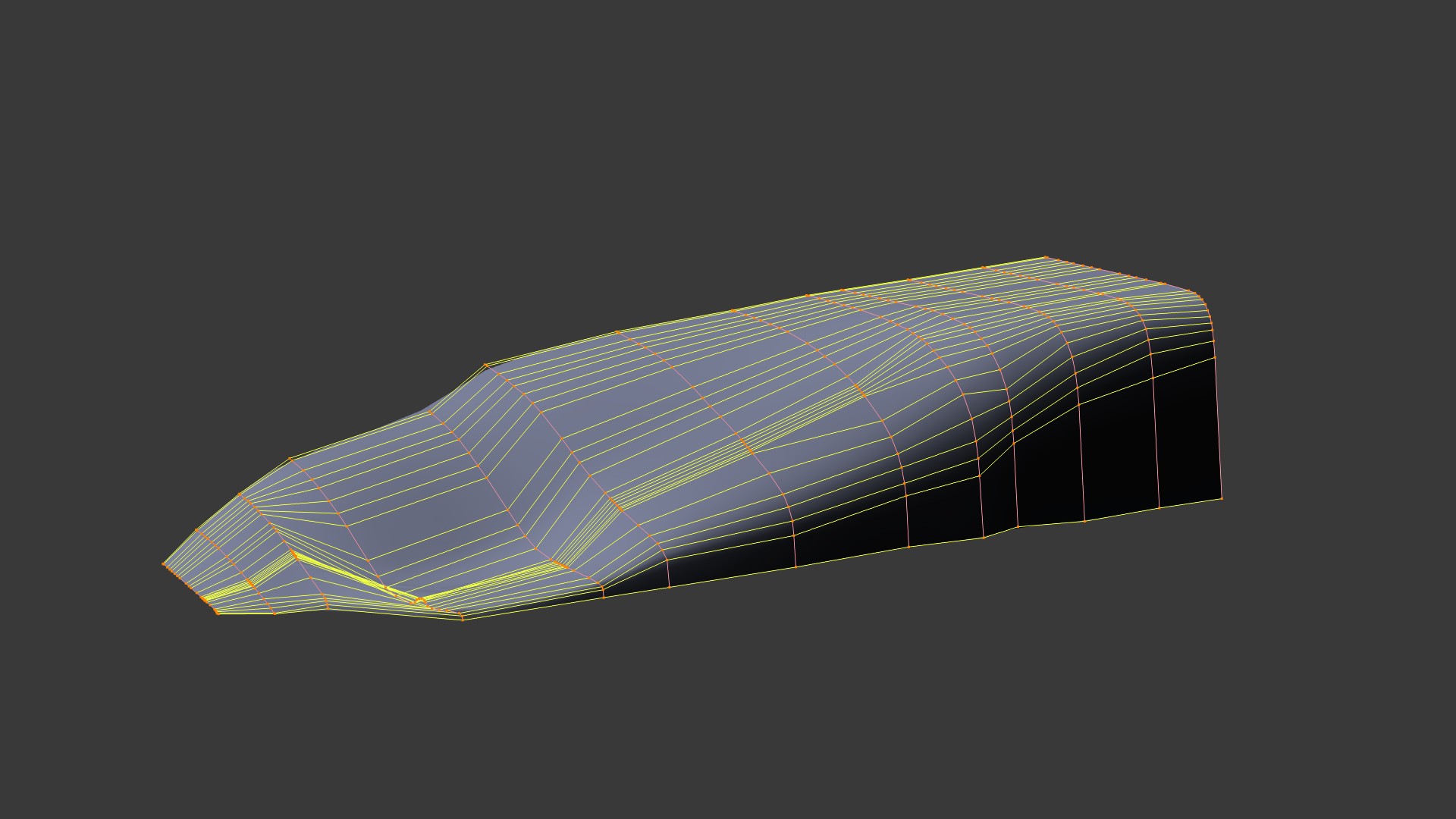
here is example using mesh verts
this is far from being smooth and like the real thing
I could add a subsurf on it but then you loose the real shape !
so it would be interesting to know if there are good tricks here to get a more exact and smooth shape
thanks
happy bl
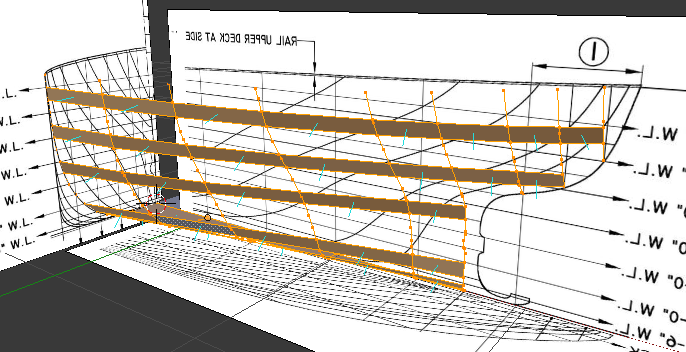
Actually the drawing you are working from is not bad. It lines up quite well. Start by placing the orthographic view on a Empty. Place them relative to each other. Then lines become easier to see.
It is recommended that you use Water line (W.L.) and Buttock line to find the point in space. After all this is how Ship Hull Design is passed on to the shipwright for him to build it. Smoothness of hull has to do with shipwrights eye! Connect those points and start to form a hull. It will be some what bumpy but it can be smoothed out. Right?
good idea to use planes following the global axis
i’ll prepare a test file
but I don’t understand why there are more lines on the bottom drawings then the 2 others
even the qty side lines are not the same then the qty front lines for the cross sections
so this is really difficult to align anything !
how do you link these lines in 3D?
one trick if I don’t use spline skinning
might be to use Bezier curve to have smooth curves then convert to mesh lines!
but will test that too!
this drawing is not bad
but many times when you get small dwg from web there are some distortions and usually very small
so not always good quality high res !
often the lines are so tick that you have to be careful where you locate your data points too.
thanks
happy bl
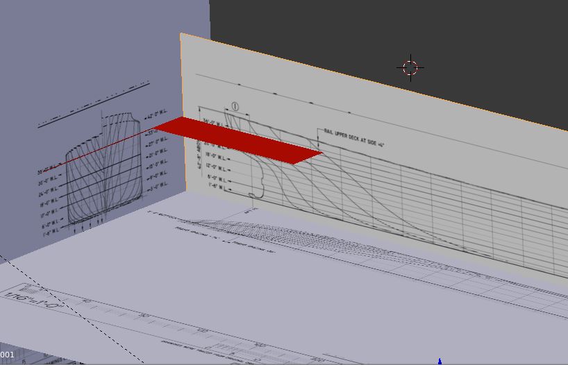
did a new set up in 3D
you added the back lines near the front or middle
is it the proper way to set it up ?
happy bl
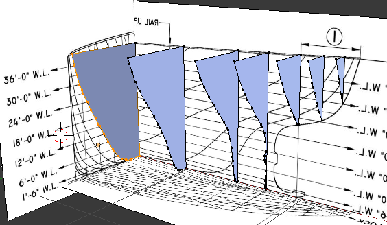
In design drawing like this, each hull section lines corresponds to other views. They all represent 2D slices of the hull. There are no extra lines. So the trick is to find which line go with which section line in other view.
In this case I just used hull front elevation slices with side elevation to create each section in 3D space. Each view was carefully scaled and placed so that there section lines all fit to gather. Then axis of each image view was locked. No accidental misalignment!
something confusing here
but why is there like twice as many lines on the bottom then the other 2 ?
and number of lines on elevation and side is not the same!
and you did not use the bottom !
we also assume that on the grid the distance is constant
I guess and there is one cross section per DX !
will try this again
may be use some Bezier curve with lot of points to follow the worst curve cross section smoothly
thanks
i’v skin it with the back cross section
and one of the curve is not right
will see why it is not!
thanks
why is there like twice as many lines on the bottom then the other 2 ?
Study the drawing closely and project all section intersection points. They all project properly. No extra lines.