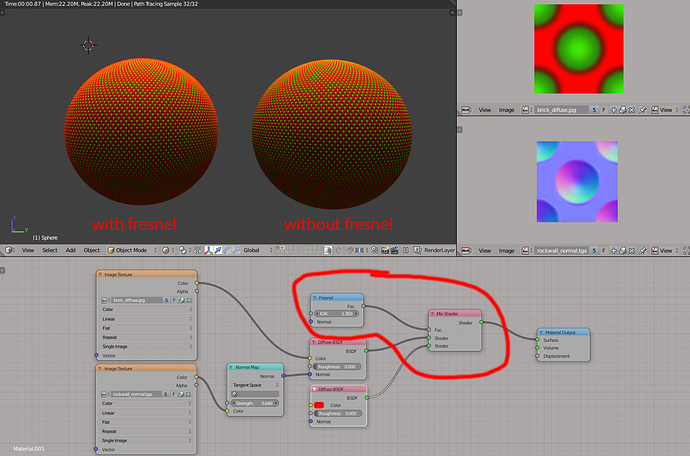
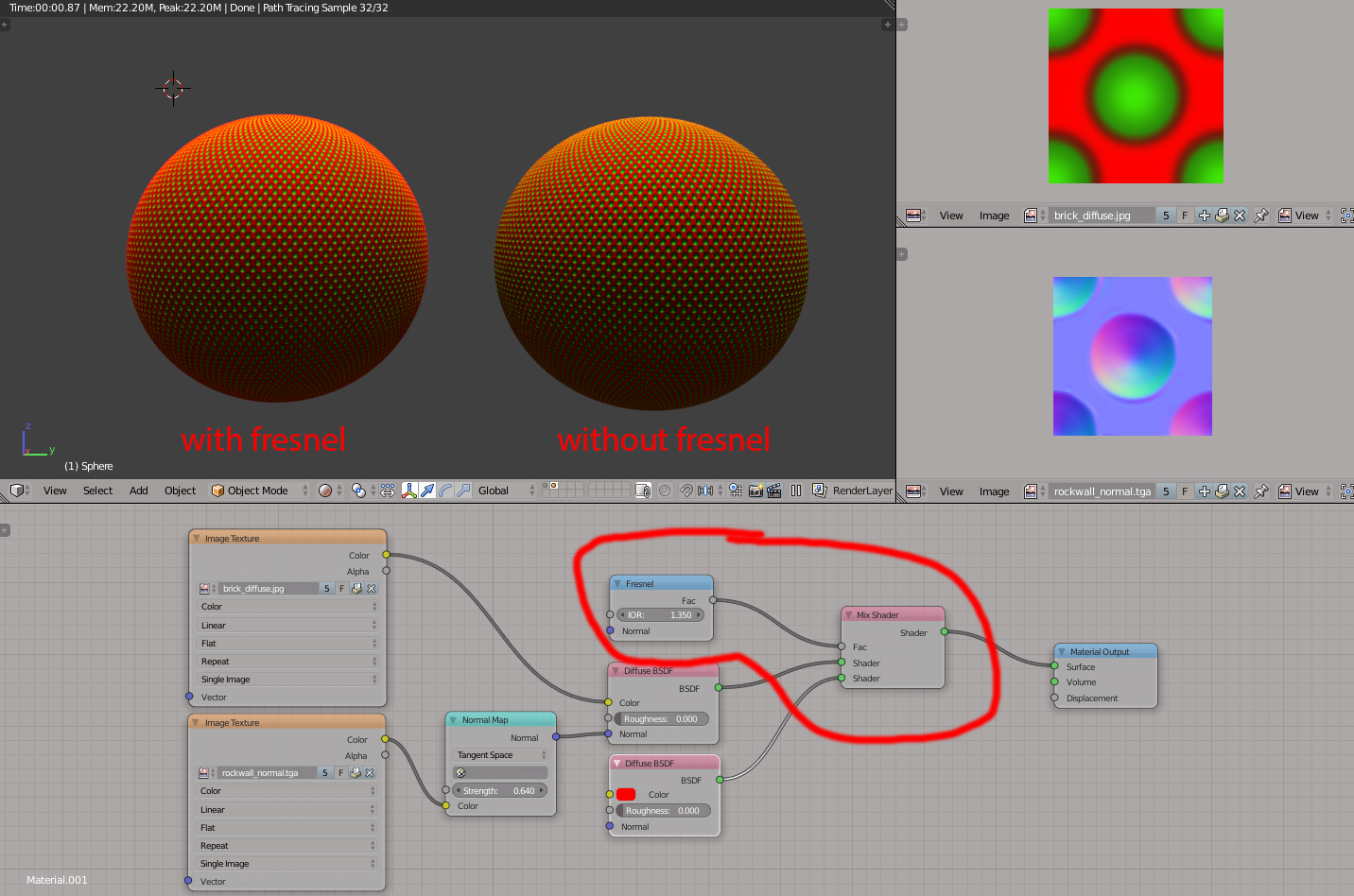
First picture shows a microsurface made with a bumpmap with the nodesetup similar as shown on the left.
-Second picture shows the result I expected, because the green dots are deeper into the surface ( via bumpmap) .
-Third picture shows the result which doesn’t show the expected result at all.
I started very excited with this test. It means that if it would work, I can “make a shader by manipulating microsurface”. It turns out it didn’t work, and implies a lot to me like; we have to use tricks to render everything what uses bump.
Is there a way I could make this work. It would mean a lot of possibilities outside of using shaders.
@RickyBlender
What I want to do is using a micro structure for surfaces to manipulate things so that it is more physically based. I mean it is more physically based that way than using Z-depth. Z-depth is more to manipulate DOF or desaturate things that are far away, not to make materials.
It also implies a lot of possibilities if the bumpmap as shown would work: I could assign the deeper dots to another shader, color, reflection, roughness etc etc. It would be more physically based than some other ways to make materials.
If it doesn’t work, making a really good fabric shader would be impossible when using bumpmaps; the bumpmap is not rendering as “it should”.
So my question is; Is there a way I could make the bumpmap work as I expected.
For example this is real geometrie, and not a bump map.
And now it shows accurately the effect what I expected which I couldn’t do with a bumpmap so far.
so @RickyBlender, if you could make plain sphere, subdivide is 2 times, and show me how I can get this effect with a only a bumpmap ( no tricks with layer weight or post processing) instead of using real geometry. So that the grazing angle appears more pink, and the facing angle relatively more green. I would jump 2 meters high.
An earlier experiment showed me the same conclusion.
That was an experiment if with a bumpmap I could make material give colored gloss. That failed as well:
So now I am going to make this with real geometry and check the results.
TADA !!
This is real geometrie, not a bumpmap. It has a very simple material: a dielectric as you see on the node setup. It looks metallic right?
So now I found out the reason why satin looks metallic:
The colorless reflection bounces inside the ridges, and return a colored gloss to my eyes.
We cannot do this with a bumpmap. If we could do that we didn’t have to cheat by making satin with a colored rough gloss node.
Still my question is , “Is this possible with a bumpmap instead of using real geometrie?”
Yes and no. Using only the bumpmap, it’s not doable without some expensive tricks. Bumpmaps don’t occlude themselves, and this is particularly noticeable when the angle between the incoming and the normal becomes bigger. For that to work, you need to undergo with some parallax occlusion to hide the parts that should be occluded by other parts of the surface more near the camera.
In your first post, the amount of green you see at grazing angles should be almost none, but still there it is. If you think only on the uvmap, each point will linearly follow the uvmap, and since the uvmap drives the normalmap and not the other way around, then green parts will occupy the same relative percentage as if seen from a frontal view.
Most of the times, you don’t need so much detail, and you can fake the sene with the layer weigth, or have two different bumpmaps, one for facing, the other for the sides… There’s a thread, I think from Varkenvarken but not sure, where he explores a bit of the math to set a more realistic aproximation to the amount of light that is reflected, absorbed and gets through the fibers (it’s not so complicated). I remember he draw the profile of the fibers, and measured the angles that a ray could hit a fiber, or pass through, and calculated the percentages according to the angles. I think that was an interesting approach, first because for cycles, dealing with statistical information is faster than calculating a more precise result (the shaders do this, and IMO its a good way to create materials); second, because it’s easier to create exactly what you need, and it’s faster for the artist to setup a good looking material.
Unfortunately the OSL script didn’t do what I need for some reason. It was fairly easy to setup, and it did something. OSL shading checkbox was checked on, and rendering on CPU. I placed a mirror to see if there was something.
The green dots are laying deeper in the material via a bumpmap, and I should see more red at grazing angles. But also this is yellow ( the mixture of green and red) at grazing angles ( at the end ).
So I will find something about parallax occlusion .
I noticed that you were having trouble with my old Modbump setup, the issue could be because you’re using an old version of the node (containing issues that have since been improved upon or fixed).
@Ace Dragon;
I am so happy with your modbump, I can’t imagine living my blender life without it. I struggled so much with those black artifacts that I thought that cycles would be to limited to me. Something like this should be build in blender, together with the IOR flip from greg zaal and the reflection nodes from cynicat pro. And if we could make a bumpmap so that we don’t need parallax occlusion… wow… Cycles would be the paradise on earth for me. ( Is already).
Here a comparison of a bumpmap without modbump, the old version and the new version. Note; modbump solves the problem with the black artifacts when using bumpmap, but doesn’t do parallax occlusion which could be a solution for my question of this thread.
The goal I had in mind for Modbump was mainly just getting rid of the black artifacts when using bumpmaps with glossy shaders. Preferably though, someone would write a patch for Cycles that takes care of this automatically through the bump node (ie. either omitting the data or writing better quality data than just a black color).
Also, since parallax mapping is only a visual trick (that breaks down at very steep angles), the only real solution for a true 3D look is displacement, which will mean high memory use until Mai’s micro-displacement project is complete and in Cycles (see the thread in the General Discussion forum for more info). I would also note that the limitations inherent in bump/normal maps is a general thing across all render engines (so trying another engine will likely not help).
Ahh, look that is useful information and I can take a rest. I had in mind to take a look at the micro-displacement which I have downloaded but just tried it once. Good to know that parallax mapping is breaking down at steep angles, and that all render engines have limitations with bump-maps. If micro displacement is not a solution for me, I will take a look if I can do something with copying group instances which seems to be memory friendly.
Below two renders with same material, same texture. One is done with bumpmap the other done with the micro displacement build. Interesting to see how geometry changes the behavior of the material.
But it doesn’t work as well on a flat surface, it would require more trickery with camera view angles etc.
I’m curious as well, about how you managed to get your result using that microdisplacement build. If you can share some print’s I’d be thankful!
EDIT: nevermind, just managed to do it seeing this tutorial:
But it is limited to CPU… the only advantage is that it is faster, so you decided to use it because you could have a highly detailed mesh without having to subdivide it a lot, is this correct?
@RickyBlender , what file, with Suzanne, the cloth or the plane with dots?
@Arkhangels, I wanted exactly to study the behavior of fabric in the first place for my fabric shader. I am working on a fabric shader.
Great trick with the fresnel. I think I can use that for fabric.
Oh yes, I did those renders on GPU with the micro-displacement build. I think in the video he is using an older build. It seems there are fewer options as well but more stable. My pc has to work hard for it , so I think I am not going to make my fabric shader for that. Maybe I use your parallax occlusion instead, if the render time is ok. It seems better than just a bump map.