No, it’s not guessing at all! It’s calculating. You saw how well it works. Please do open the GitHub issue and we will work on your idea.
Trying this wonderful tool again but have issues getting camera correct. Cause of the camera angle and flat back plane i think. I get the angles correct, but the scale is way off
The Bonaldo sofa is 2.80 x 1 x 0.68m. Im not 100% sure about this cause this thing is modular. So all kinds of variations is possible with different measurements
I read that if a plane is parallel the result is very difficult.
Perhaps some of you have more luck and would like to help out here 
Attachments
Hi rombout
Yes, it’s difficult. I tried the radiator as the rectangle with “Solve Focal” and it kind of worked, but perhaps the radiator is not mounted completely parallel to the wall. You could also try “Solve Focal+X+Y” which allows for undistorted rectangles. However, you would need the two dangling vertices and I don’t see how you could align them.
Yes, i know i tried that as well. But those need to have a angle right. I get a error if i use just move them over to the right. I sort of got, it a bit off and i tweaked it some more
Attachments
Hi Rombout,
I know it is more then two months later, but maybe you find this interesting for another time.
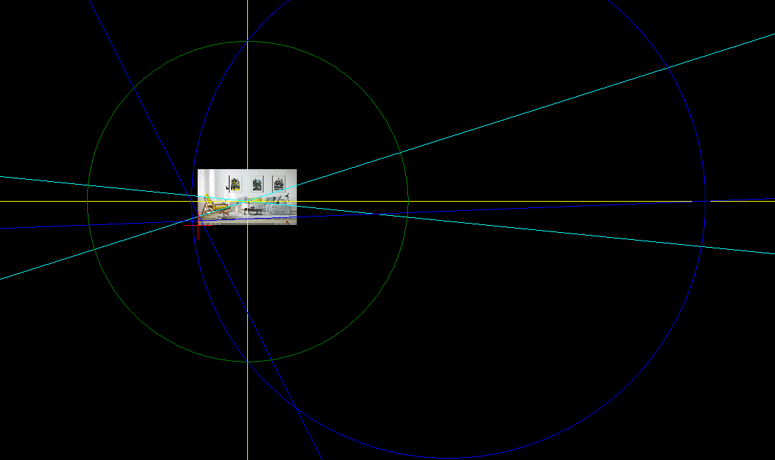
The image you posted is in ‘one point perspective’. The verticals are perfect vertical, the horizontal lines are perfect horizontal.
I give an example made with LibreCAD.
You can find vanishing lines that go the center (cyan). Now we have the vanishing point. This point is in ‘one point perspective’ also the center of the image. Then you know the horizon lines (yellow).
We want to find the ‘diagonal vanishing points’ of the image. The chair has two own vanishing points (blue lines) that are on the horizon. Now we make a (blue) circle between the chairs vanishing points. The blue circle intersects with the vertical yellow vanishing line. Because of Thales’s Theorem, we found the diagonal vanishing lines that give a 90° circle of view (green). This circle cuts the horizon. we found the diagonal vanishing points in the image:
With this information we can setup the framework that the camera calibration add-on can use. Here I give the rectangles:
Use here Solve Focal+Y, because the verticals are vertical.
Example.
I hope this information is useful.
Marcor,
Another information, now for ‘two point perspective’:
For “Calibration of focal length, vertical lens shift, position and rotation (Solve Focal+Y)”, you need more information to find the ‘principal point’.
Now, throug the camera, everything looks okay, but the 3d model can be very different from the “real world”, when the ‘principal point’ is on another place on the horizon-line than your algorithm assumes.
For solving the real 3d proportions of a ‘two point perspective’, you have to now the ‘real world’ proportion of one rectangle or you have to know an angle based on the ratio of a rectangle.
The information that you can find in the link beneath, is a pdf written by Erich Hartmann, a German mathematician from the Darmstadt University:
‘Darstellende Geometrie für Architekten.’
Page 126 gives an exercise with illustration (Aufgabe 5.23), to find also the ‘principal point’. (Hauptpunkt) amongst other things.
Page 181 gives the solution.
So because you know the angle α, you can find the ‘principal point’ (in illustration: H). With this principal point on the right place, your add-on can give a proper result.
This pdf gives much more interesting information about perspective.
I hope this information is useful. Thank you for your nice add-on.
Thanks for the addon. Noticed that I can get different results depending on where in the image the rect is aligned. From both Solve Focal and +Y. Would multiple rects increase accuracy / certainty / average things out?
Hi iarga
Thank you for your interesting message (and for the great PDF).
Let us compare the 3 different modes of the plugin:
- Solve Focal assumes that the principal point (Hauptpunkt) is exactly in the middle of the image.
- Solve Focal+Y assumes that the principal point is on the vertical line in the middle of the image.
- Solve Focal+X+Y makes no assumption about the position of the principal point. It can be anywhere within (or outside) the image.
You are therefore right in saying that the +Y method lacks information if the principal point does not lie on the vertical line in the middle of the image. That is why there is the +X+Y method which makes no such assumption (and which requires more information).
If you have a different opinion about this, please let me know.
marcor
Hi LoboTommy
In ideal conditions the result should always be the same. However, the real world often is not ideal. See a list of “things you should know” in the README. Yes, in principle, some of these effects can be mitigated by averaging of “fitting”. The add-on does not support this.
It would be great if you could post the image that you are having problems with.
marcor[](https://github.com/mrossini-ethz/camera-calibration-pvr#things-you-should-know)
marcor, thank you for your answer.
Solve Focal:
Works great with three-point-perspective with ‘principal point’ in exactly middle of the image.
In other words: pictures, from a ‘regular’ camera, that aren’t cropped or ‘perspective corrected’.
Solve Focal + Y:
Works great with two-point-perspecive with ‘principal point’ on vertical line in middle of image. As you said in your manual on Github and here above.
In other words: it works with images that are corrected for architectural distortion, with parallel verticals. But this ‘perspective correction’ must be only in vertical direction (and no cropping). With corrections in other directions and/or cropping, the ‘principal point’ is not in the middle vertical line of the image.
Solve Focal + X + Y:
Works great with three-point-perspective when ‘principal point’ isn’t in center of image.
In other words: it works with images (with three-point-perspective) that are cropped, but there must be no parallel lines.
So the difference is: three-point-perspective and two-point-perspective.
Solve Focal + X + Y: doesn’t solve a two-point-perspective. (“edges must not be parallel”).
Solve Focal + Y: does solve a two-point-perspective. (but only with ‘principal point’ on vertical line in middle of image).
So what I wanted to make clear in my prevous message is: If we want to deal with an image with two-point-perspective, with the ‘principal point’ not on the vertical line in middle of image, we need more info from the ‘real situation’.
This is explained in the pdf I gave in my previous post. (exercises on pages 126 and 127, with solutions on pag 181 and 182).
Without this extra information, no algorithm can find the ‘principal point’ in a two-point-perspective image. (when ‘correction’ is not only in vertical direction).
So if we are in the happy circumstance to know more about the ratio of the sides in a rectangle or an angle specified by this ratio (rectangles as explained in the mentioned pdf), we can find the ‘principal point’ in a two-point-perspective.
When the ‘principal point’ in a two-point-perspective is found, but is not on the vertical middle of the image, we can (for example in GIMP) extend the ‘canvas’ of the image (don’t scale original image) so that the ‘principal point’ will be in the middle of the newly created image. After this procedure we can use your add-on with ‘Solve Focal + Y’.
So it is really great to have this ‘Solve Focal + Y’. For it can deal with parallel lines, therefore two-point-perspective. The other two options can’t deal with parallel lines, so they can’t be used with two-point-perspective.
I hope my answer isn’t too tedious, I just want to be as clear as possible.
Hi iarga
Excellent! You made your point perfectly clear and you are quite right. I was wrong because I implied that you could use Solve Focal+X+Y in a two point perspective.
The question now is: What can be done about it? Do you think giving the ratio of the rectangle would be enough? I think it should be.
I also think that I will have to change the user interface to distinguish between 1-, 2- and 3-point perspective. (There should be a solver for 1-point perspective!) I am not sure, however, whether the average user is going to like that.
marcor
marcor, thank you for your attention.
For two-point-perspective:
The rectangle (as showed in exercises of the pdf ) used to indicate the ratio or angle, should be parallel to one of the three planes that are specified by the rectangle and dangling line of your add-on.
it can’t be a rectangle in a xyz plane ( for example an inclined roof or a window on an inclined roof).
So the known rectangle for the ratio should be parallel to:
- xy plane or
- xz plane or
- yz plane,
[INDENT=2]specified by the rectangle and dangling line of your add-on.[/INDENT]
Also the sides of this known rectangle must be parallel to the edges of such a specified plane.
Of course,if you know the ratio of the rectangle used by your add-on, this is sufficient. But sometimes you only know the ratio of, for example a window, From a window you can’t extend an edge perpendicular to the window (plane), for you can’t see a perpendicular direction.
Also most windows are small for proper finding the vanishing points, I prefer a big wall (rectangle), because then I can work more accurate.
Further, it would be very useful to have the possibility to give a ratio given by a known rectangle in or parallel to the ground, floor. (for example tiled floor).
Maybe it is possible to show a seperate rectangle as in the exercise from the pdf, wherein you can give ratio or angle, that corresponds with another seperate rectangle in the image? I think this is rather complicated to achieve.
For one-point-perspective:
Here is also need for a known rectangle, parallel to floor, ground, or side wall.
The wall that is perpendicular to the line of view, is useless.
- See page 124 and 180 of pdf Erich Hartmann.
- Or a something with 90 degree angle as I showed in a reply to rombout.
[INDENT=2]
(if the chair was not rotated, then no solution was possible in this way, It is an assumption the chair legs form a rectangle. My example with the one-point perspective is not totaly accurate, because I didn’t extend the image a few pixels, because of the principal point is not exact on the middle vertical line of that image.)
[/INDENT]
In three-point-perspective no ratio is needed. The vanishing points give enough information.
At this moment the nice thing of your add-on is the simplicity!
So, more functionality may cause confusion also. If you want to have an add-on with all this functionality, maybe you can better create something new for ‘advanced use’ ? But I’m no coder, so here I can’t give advise. I’m just a simple user.
My primary goal is not to provide you with a lot of work. My primary aim of my posts is to show that it is possible to prepare an image with LibreCAD or with Geogebra and some knowledge of geometry and perspective, in such a way, that your add-on can be used. But preparing images in this way, takes much time. But it is also rewarding, because now the image is usable.
When we have (a) proper three-point-perspective image(s) of an object, we can model something. We can use now the 3d model as reference. Then we also know ratios of rectangles that we can use in one- or two-point perspective, when modeling with more then one image.
Hello marcor
Thank you one more time for such great tool, sometimes it is very helpful!
Just one question. Is it possible to use not only one image? What if we have several photos of one object from different angles. How do you think is it possible to align automatically camera to geometry? Or it should be done only manually? Thank you!
Hi marcor. I’ll share a blend with an image packed (a random candidate from the net). It’s marked where I placed vertices down to the pixel. Six different rects with some correspondences between are listed in the text block. Also below:
Rect        Mode           Focal Length mm

Cyan       (SF)        =    64.8086 mm
Magenta  (SF+Y)   =    64.7373 mm
Blue        (SF)      =    60.0602 mm
Red        (SF)       =    53.7274 mm
Green     (SF)       =    43.4901 mm
Yellow    (SF)       =    43.7927 mm
It’s nothing show stopping here, but if it interests have a look by all means.
Attachments
pvr_Tests.blend (329 KB)
@Marcor: thanks for addon  Just impression -seems to me more natural calibrate vertical plane (building fasade) from front view with “Vertical orientation” result.
Like if I need calibrate
-
Horizontal plane (floor) – I start from TOP view
(script works like now) -
Vertical plane (fasade) – I strat from FRONT view
(vertical orientation by default)
So the script can recognize what orientation to use from used view automaticaly and set orientation whitout user attention.
It’s a small thing, that is shown in a gif (not described in text), but why to study something that can be solved by script
(if its too hard, or it ruins all the proccess, leave it its just a thing that I needed to search for a first touch with script)
Or maybe to start in both cases from front view, that is in most cases more common shooting angle or photographer position (vertical).
Or its totaly bulshit
Hello everyone!
Allow me answer the 4 posts in one go:
iarga: Thank you for your post. I agree, that the simplicity of the add-on is important and I think that a two point perspective with a x-shift is rather rare. Adding a ratio for the input rectangle would be simple (from a UI point of view). A seperate rectangle would be nice, I agree, but usability would suffer (I think). I have created 2 feature requests on GitHub. Let’s take the discussion there.
Legofon: I am sorry, but this is not supported. I don’t think it will ever be. Try to do it manually. Good luck!
LoboTommy: I have created an issue/bug report on GitHub and will look into it when I find the time. Thanks!
vklidu: I think that’s a great idea! I created a feature request on GitHub, let’s take the discussion there!
Thanks everyone for your interest!
LoboTommy, did you also try “Solve Focal X+Y” ?
Thank you for your efforts marcor. With only a single view many assumptions can or have to be made extrinsics and intrinsics wise. With ratios and or edge lengths you’d have more data to solve with.
I have yet to employ SFX+Y successfully iarga.
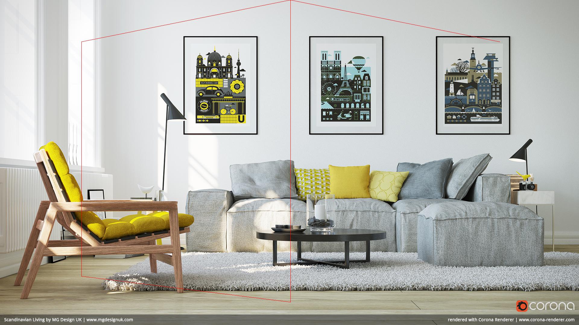
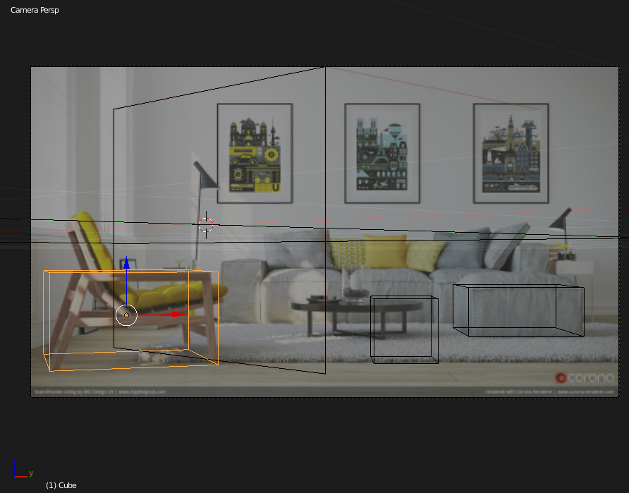
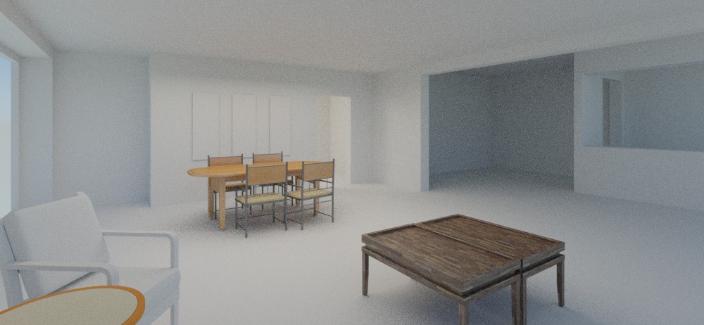
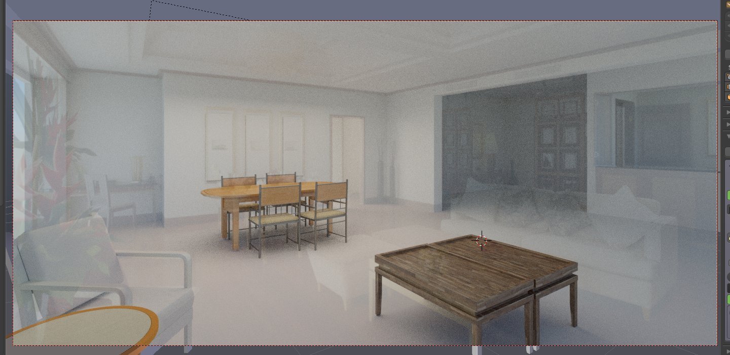
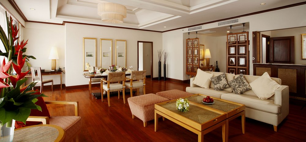
RickyBlender pointed me in the direction of this addon as I was having problems with Blam!
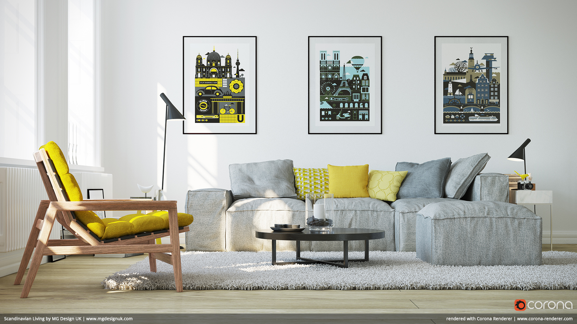
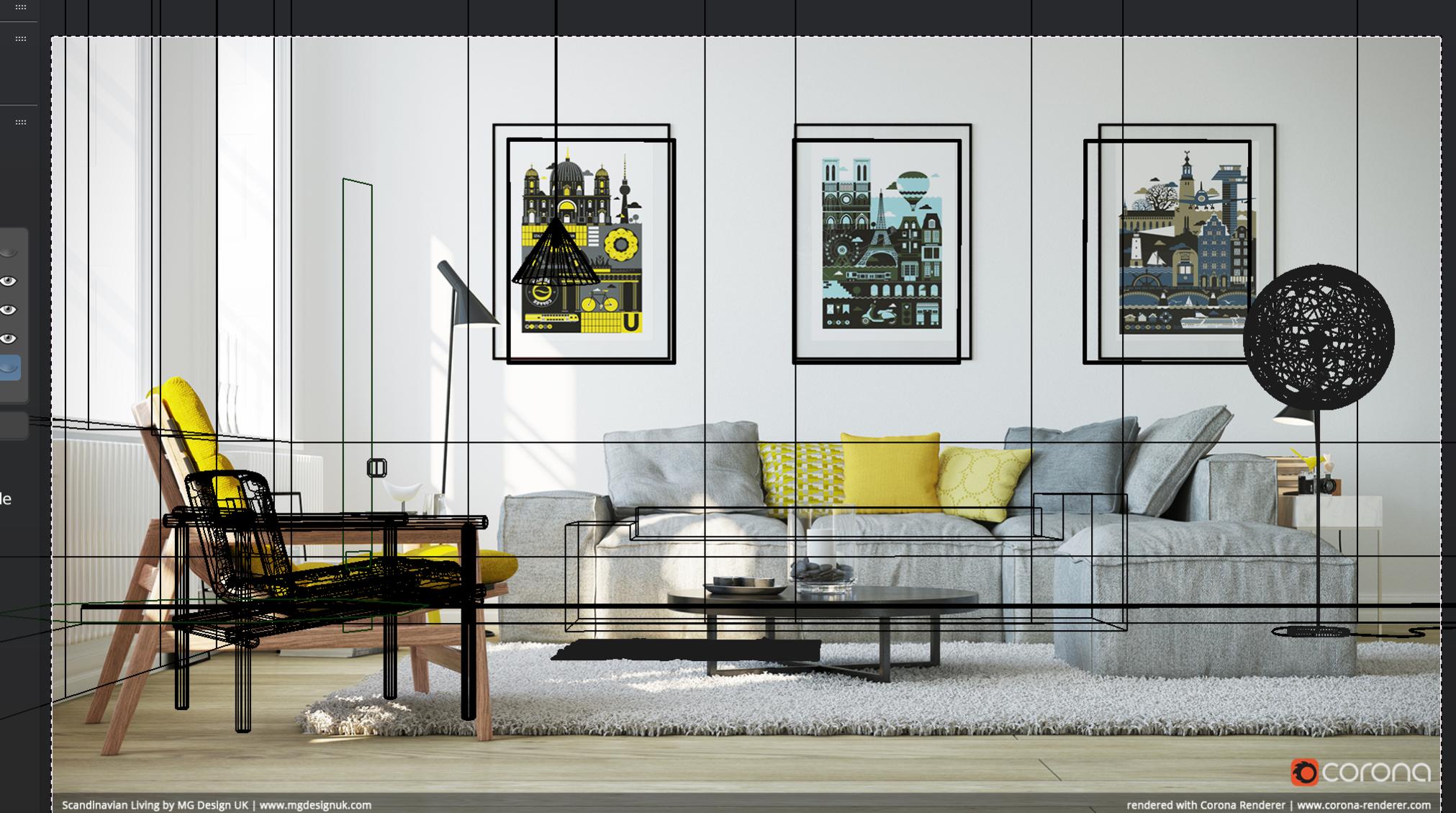
Using the Focal+Y solution, it gets pretty close to a match, the closer object show the focal length isn’t 100% accurate, but it’s close enough, once I’ve scaled the room to a logical size, that the difference isn’t major.
It’s my first stab at doing this sort of “room from an image” modelling and I have to say, this addon makes it a reasonably pain-free process, many thanks.
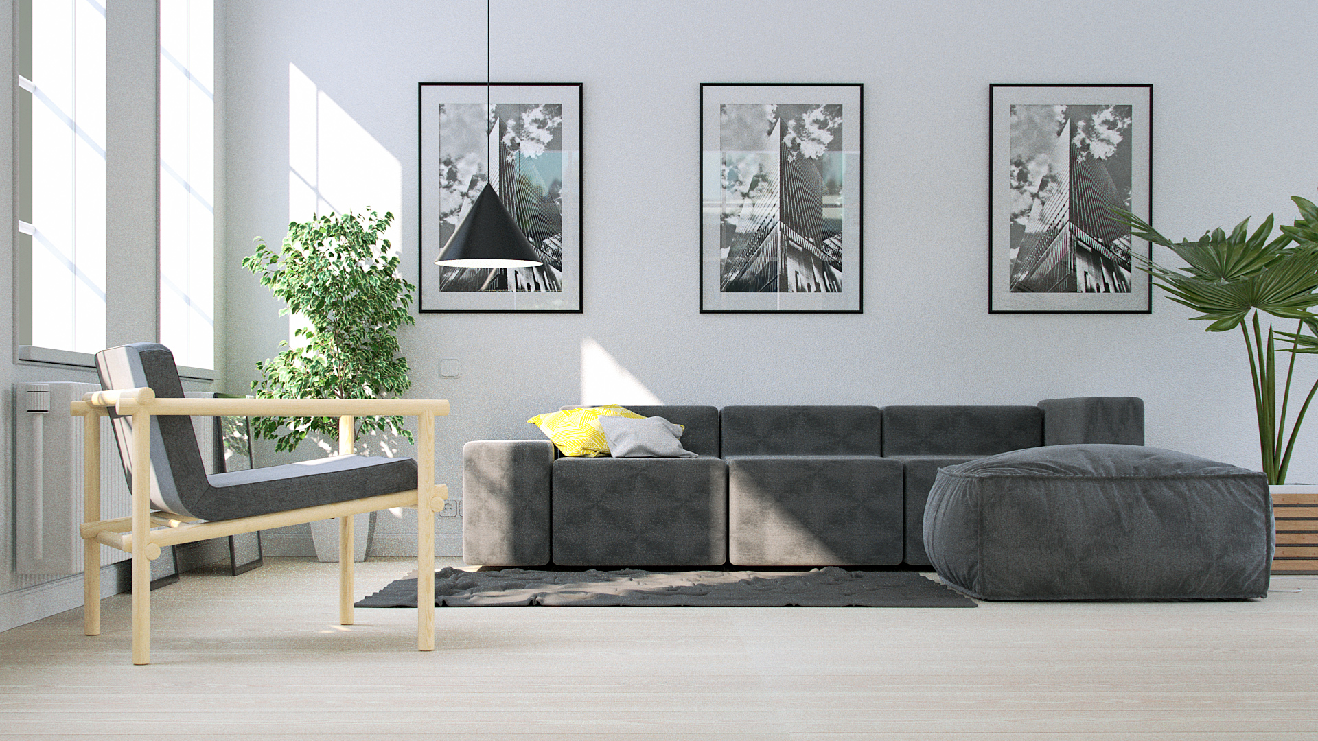
Here’s my attempt, Ref img, room model then room with ref overlayed in viewport. Obviously a long way to go with furniture etc yet. :eyebrowlift:
Attachments
Nice try, are you going out do all the models