I’m currently in the middle of migrating my custom Looks/Materials/Shaders library to Blender and I need some help figuring a few things out. The one that’s on the front burner now is how to apply a colour ramp (or the likes of one) on the specular and/or the general luminance of a shader so that I can get varying colour bands from the hottest point to the coolest on the surface of a given model.
Typically, on other software packages, I’ve used a utility that samples the luminance and maps a ramp along that going from 0 to 1. Or, calculating the dot product from the surface normal to the light source. You get the idea.
I’ve discovered several ways of getting the normal-to-camera dot product in Cycles using the node editor, but haven’t been able to find out how I can achieve a normal-to-light and/or luminance re-mapping.
Any help from the community would be welcome. I’m stumped.
No. Sorry. I want this too In practical terms, how do you obtain this dot product for a donut light source? In a path tracer, this can’t be done. But yeah, even if restricted to only (shadowless) point lights this would be very useful for mixing/adding shading effects.
If you’re doing just point lights without shadow, you can emulate them inside the shader itself. Basically you would have to create the calculations inside of the shader; if I understand it correctly, you would use the normal, position (of the surface), incoming direction, and a vector representing your point light’s position (I think that is it; might be forgetting some details though), and then do all the math with nodes, and feed the output into the color and/or strength inputs of an Emission node.
I think you might even be able to use drivers to make the vector on the noodle correspond to the position of some actual object (an empty, or possibly even an actual light if you’re using it for other things as well).
To ago, what you’re suggesting is to put the colour effect I’m talking about on the light shader itself. Interesting.
I’m also interested in finding out more on how you’d do the math with nodes. As I’m new to Cycles nodes, I need some help here. The math I can handle. The implementation is where I need guidance, if you’d please.
You right click on the parameter you wanna add a driver to (like for example the color components of a RGB node), and select Add Driver. Then you open the Graph Editor and switch from f-curve to drivers; then you can edit the selected driver on the Properties shelf (press N with the mouse cursor inside the Graph Editor to toggle it).
Tiago, you gave me some good leads. I’ve already come up with some code. Now, I have to implement them in OSL, Python Nodes and through drivers and math nodes and see which yields the most useable results. I don’t have to tell you why it’s worth the effort, as most CG artists understand the reasons.
I know that OSL nodes won’t be rendered on the GPU, but perhaps I’ll familiarize myself with the inner workings of Cycles and see if I can do something about that in the future.
The more I use Blender’s node system, the more I like it. I’m glad I migrated over to Blender full-time.
I may have to ask some other questions to the community as I go. There’s a lot of ground to cover in my materials migration.
it’s kind of possible with a shader that is only available through the OSL api. Not really for specular, but it’s a diffuse shader. It’s called the DiffuseRamp and it can handle 8 different colors based on the light intensity. Check the http://www.openshading.com/ from Thomas Dinges. He has a shader there that can be usefull.
the shader is built in in cycles, but not available as a node… don’t know why
Tiago, what I found interesting in your example is how you fed the Ico position driven into the RGB of the color node as input for the math that ensues. That feels familiar to me. I’ve been doing so through other python means, which also yield results, but there are benefits to each method, so I appreciate you showing us this.
It gives me an ideas. As I said, I only just started learning Blender node editor and Cycles a day ago, but I’m making progress. Helps to have experience, I guess. Helps A LOT to have community support, as well.
Thanks, Secrop. Already checked it out. The code is helpful, indeed. Anything to give me information on how I should be handling materials in Cycles helps.
@TiagoTiago: Wow, I’m thoroughly impressed. Love the possibility to control the diffuse terminator. Specular doesn’t seem to roll off properly/at all, but I’m guessing it’s simplified code (my brain is too incompatible with vector maths anyway, so I can’t really check). But still, it’s a very nice proof of concept.
Not sure how useful this would be, as I find having to deal with drivers and their “trusted source” (oohh, scary :)) a bit too awkward. But its a nice wakeup call on what can be achieved if willing to put in the hours needed.
For the specular, I tried to replicate the formula described at this page. I tested replacing the material with an actual Cycles glossy shader set to Sharp, and it looks like up until the terminator the center of the blob is where the reflection should be, and it does cut precisely at the terminator the same way (the smaller the light source, the more abrupt it cuts, and since this is a point light, it’s precisely at the terminator). There is some weird behavior close to and beyond the terminator though (the beyond part isn’t important for doing things realistic-ish because there shouldn’t be a reflection there anyway; and NVidia’s code on that page seems to block the light there anyway); it’s a bit more noticeable on big flat surfaces though. I couldn’t figure out how to let you control the terminator for the specular without producing weird results.
The trusted source thing is because of Python; it can do pretty much anything an actual program could do. In this case, the cocern isn’t necessary because pretty much all the python in this scene is the just assigning the values of the drivers (not even calculating anything); but without inspecting the scene more carefully you wouldn’t know for sure there isn’t a virus hidden somewhere.
Tiago, I have a question. How is it you use an Emission shader on a surface and not a light? I’ve seen this before in other examples and I’m just not getting it. I’m coming from a deep RenderMan background, by the way, if that helps you understand my situation better.
Also, so, your specular formula is sound, however the math nodes seem to have everything there for you to implement any other method. The only math node not available, it seems is pseudo light source vector. Correct me if I’m wrong. And that would be useful, I think.
Using the emission shader on objects makes it so every point in the surface of the object is a light source. I did it like that that so that I had more direct control of what color the surface of the object should be; with emission shaders (as long as you’re not mixing with other types of shader) it’s sorta like you’re outputting the colors directly to the screen instead of letting the engine figure out what color it should be (but if you have other materials on objects in the scene that use other shaders their color will be affect by pretty much all emission shaders that can see it, as well as other things like diffuse, glossy and refract bounces etc). I’m not really familiar with RenderMan though, not sure how I would explain it in RenderMan terms.
For the pseudo light source direction I subtracted the pseudo light source position from the surface point position. Any vector or color node where you can edit the values would suffice, all you need is the ability to manually enter the X, Y and Z values; the RGB was just the first one that came to mind. Now you mention it, I could have used a Vector Math node in Add mode and leave one of the vector values at <0,0,0>, putting the pseudo light source position in the other vector.
What would really help would be a node with actual Light Ray Direction output (we already got Ray Length that would provide the position if we combine it with the direction information). With that we wouldn’t need to be restricted to point lights, any regular light and even things like diffuse bounces would work with whatever we try to make.
Imagine the shading and reflections off a CD. You have a regular glossy shader, and maybe a diffuse for some things. Making the above anisotropic (I have no idea how :)), you could then add those together with an Add Shader, or mix them together if you can mask out where the above will be effective. If adding, you should pay some attention to energy conservation to avoid blowing out anything. It’s obviously not perfect, but may be a substitute for missing true shading effects of this type.
Before adding the fake stuff, you can also put the emission shader into the second slot of a Mix Shader, and connect the fac to Camera light path node, in order to make that part of the full mix be only shadeless rather than actually emitting light.
I’m not sure of this is exactly what you are looking for - but I have been experimenting with something that sounds similar over the past few days.
Essentially - it works in a similar fashion to the dispersive glass, but on glossy/anisotropic reflections. I haven’t used a colour ramp though - I used three anisotropic shaders ( a red, a green and a blue) with different roughness values (blue having the lowest - red the largest) - added together using the add shader.
moony, that’s awesome! I did something like that last night! I’ve been experimenting a lot. You guys have all been giving me great ideas and I’m loving Cycles more and more. Although, I’ve got a notepad full of stuff to add to the node editor (new nodes), as I’d like to contribute code to the community.
CarlG, thanks for the explanation, but I’m afraid I don’t understand how the emission shader is used in this manner. It’s the basics of it that’s eluding me. Any links you guys can include?
 In practical terms, how do you obtain this dot product for a donut light source? In a path tracer, this can’t be done. But yeah, even if restricted to only (shadowless) point lights this would be very useful for mixing/adding shading effects.
 Thanks a lot
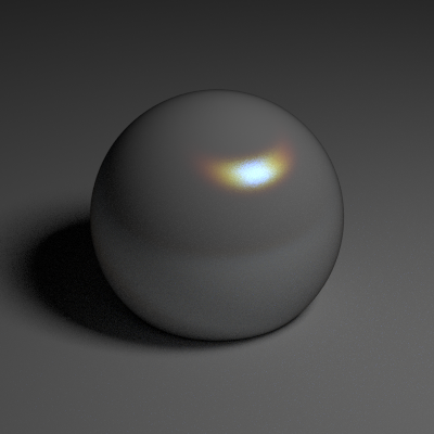
