Well Sir, I would do all this with a single Armature. Why, because it is a classic example of Inverse Kinematics for the piston, connecting rod and crank. The fly in the ointment is that the main crank, the white bits, are not normal to the crank rotation, they are at 45 degrees. So for here I would use two drivers to rotate the various parts according to the crank rotation. Here is a picture:

This means that you need to use scripted expressions. So, for my blend file to work you must check “Autorun Python Scripts” in user Prefs => File tab. Now to the drivers themselves; you want he blue object to rotate ± 45 degrees relative to the crank, so the driver for this is:
pi / 4 * sin(var)
Where var is the Y rotation of the crank bone in Local Space. All drivers work in Radians and there are 2 * pi radians in 360 degrees. so the link rotates pi / 4 (45 degrees) according to the Sine of the crank rotation.
The next driver rotates the hexagon topped bit (sort of brown colour) this needs to rotate back and forth by 45 degrees also, but along its local Z axis, so the driver is this:
(pi / 4 * cos(var)) - (pi / 4)
So, this one rotates the opposite mode to the first, so we use Cosine instead of Sine (Cosine is 0 when Sine is 1) and we subtract 45 degrees from its rest position, since it also is 45 degrees out of phase with the first one.
Then you just run the animation, remember when you stop an animation with drivers, you need to move it one frame to reset itself, since drivers effectively work one frame behind the animation (just accept that for now).
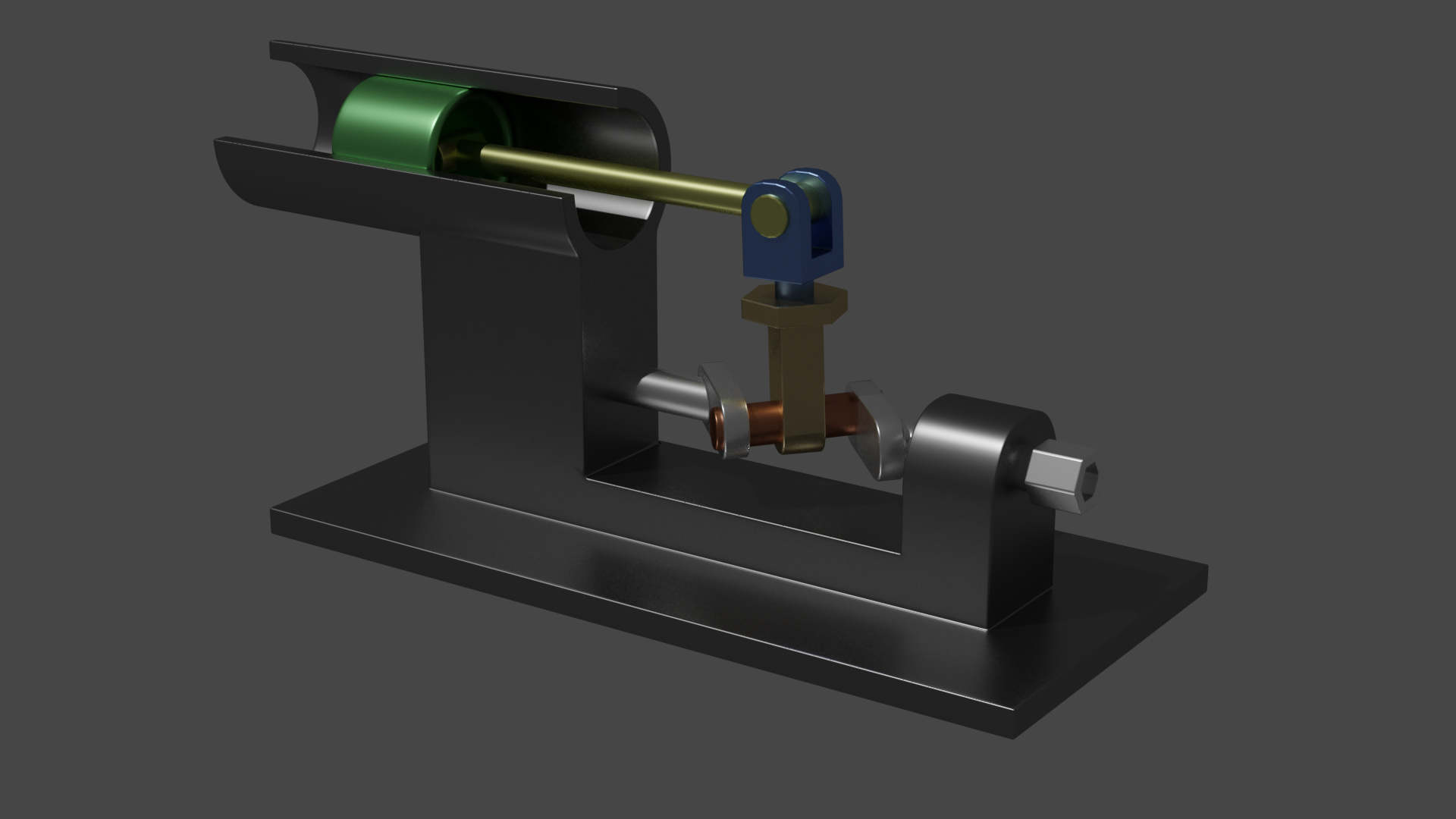
A render of the file, don’t look too closely at the modelling, it is just thrown together to show the important part of this project, which is the Armature:
Here is the Blend file: crank-thing.blend (643.8 KB)
Just press Play (ALT+A) and don’t forget to reset it by clicking the Start Position Icon twice.
Cheers, Clock. ![]()