Hi, I would like to create a similar function to Add=>Mesh=>Torus.
Only difference would be that instead of mesh consisting of rectangles, I want it to consist of vertically placed diamonds so that instead of the edges varying depending of the minor/major radius, I want to alter the diagonals. How would I go about this?
something like this? I really don’t know, just merged a few verts 
maybe give mesh addons a look, there is a twisted torus one

Yes, this is exactly what I mean. But the twisted torus addon doesn’t help me, I want the faces to be straight, like in your example.
Is it possible to somehow alter the number of segments in your example?
add a subsurf modifier…? 
no, I thought you could look at the twisted torus code and hack it…
btw, you can do a lot with just a plane, an empty and some modifiers:
>>> http://dl.dropbox.com/u/16486113/Blender/archivos/crazytorus.blend
forgot to mention: change arrays count and move empty around to change settings…
Liero, what a nice example! Indeed, unknown possibilities ==> known!
Ok, deleting and merging vertices does do the job (I’m very new at Blender), but it takes a lot of time.
I mean, is there a way to repeat the process somehow?
Ok, I’ve decided I’m doing this by hand. But now I got a new noob problem. I accidentally deleted a wrong vertice some time ago and I can’t undo it. Is there an easy way to restore it? The necessary vertice should be in the middle of the empty rectangle.

If you select the two vertices on opposite sides of the hole, you can press F to create an edge, then subdivide the new edge to get a vert back in the center. after that you can select two opposing edges and press F to recreate the faces.
Do you need anything more complex than just a tube with diamonds (eg, no twisting and crazy stuff).? I’m pretty sure you can write it as a function of
N = number of rings
n = number of vertices in each ring
D = major diameter
d = minor diameter
Here is some psuedo code…
- add a circle of diameter = D-d and with n vertices
- translate it (D+d)/4 to the side
- duplicate it N-1 times (here you will need to observe how the vertices in your mesh are oriented.
- select every other ring and rotate it pi/n radians
- select each ring and rotate it into place
- use faces_raw to add in the faces since there will be a function describing each face knowing that it crosses three rings.
but the coordinates wouldn’t be the same then? I know the basic functions of vertices and edges, but the problem is that the origial vertice in the middle was not paralleled with the edges of the hole, it’s a little bit outside.
you can model a section, duplicate and rotate around center, then repeat… I did it that way, first model a simple torus and then subdivide
but the parametric setup I showed you before gives a lot of control, here’s a version with filled faces, you can apply modifiers and join both meshes once you are done
Had a go at this using a grid and warp
Rotated it 45 on z then warped 360 to give like a rolled piece of paper with the diagonal edges touching. Looks like a triangle from front on … duped the verts rolled them to give a diagonal cut pipe cross section then used array and curve mod on a circle to make the torus.
Didn’t pay too much attention to making it “perfect” … especially in the dupe step. seems to have worked Ok… called it garden hose as the vert doubles give it that appearance. Applying mods and removing dubs leaves a torus.
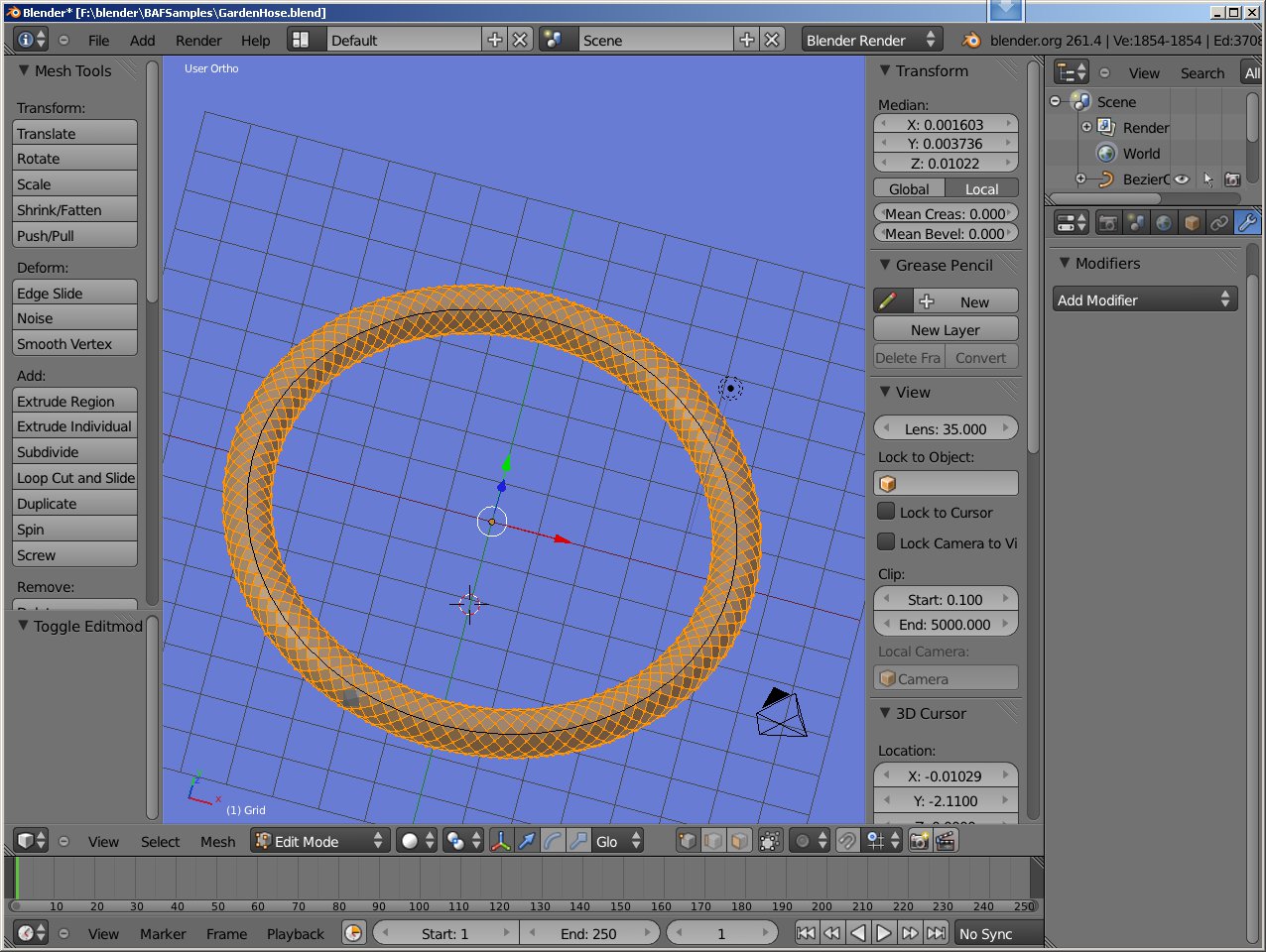
PS… just downloaded liero’s example I now know about the simpledeform modifier.
Attachments
GardenHose.blend (96.5 KB)
OK, another question. Is there a way I could display specific diamond Face Areas in some other place than straight on the face itself?
The problem is, I want to compare how different major/minor radius scales affect the areas, but while I’m scaling, all faces are selected, so all areas are selected and it’s hard to make sense. I wish to pick 2 diamonds with the largest and the smallest face areas and view their areas while scaling.
Thanks for all the help so far!
@liero You are a genius. This works beautifully. Thank you ![]()
I haven’t begun to understand how this file functions yet but I’m trying. How can this be adjusted to create four color distinctions instead of just the two (instead of:black and yellow - maybe white, red, blue, and green) but with only 3 rows (like 3 spirals - red & white checkered, then green & white checkered, then blue & white checkered, repeat, etc. - into the center)? I know this is way ahead of things but I’ll through it out here too in case it could make major impact on how this would be done. I would like to place a number on all the faces at the individual centers. I can explain why and the expected resulting torus (I already have two examples in .blend and one example in .obj built the hard way).
Just in case the explanation could help.
Please, if anyone is able to help with this - even if you can just explain how liero’s driventorus.blend works so that I can discover how to make the adjustments that I need - I’d be very grateful.
The number/color pattern is repeating so only 18 squares are needed but they need to make up the torus in increments of 9. The smallest possible size is 9x9 and I can imagine enlarging by increments of 9 to whatever blender limits. (The image below is only an example - in truth the 9’s should be in the centers of two sets of 9x9 squares making the 18).

This is for real Vortex Math / Science usage (I donate my time). Thank you in advance for any insights that you may be able to provide.
It’s been long enough  http://dl.dropbox.com/u/82843316/ParametricABHA-torus.blend this link is my best and most complete version. Thank you again to everyone for all your help. (Any size ABHA torus quickly and easily).
UPDATE: I was able to align the the UV’s exactly. Now any size ABHA instantly, I haven’t stopped rendering since I got it going. As soon as I can I’ll get a .blend up here. ( liero thank you. It works great. . . This is great, thank you again for the driventorus.blend and all of your help.)
those are just two planes and a modifiers stack, disable modifiers with eye icon to see the mesh
try to unwrap both planes, then split and load your texture in both materials, you may need to edit textures or rotate uv but I think it could work
good luck
Thank you for your reply, unfortunately I would need a minimum of 18 planes. I tried multiple layouts and no less than 18 worked for me. So, I had to divide the 2 planes into 18; 9 faces on each and then I was able to align the texture properly so that the sequence is not broken. Now, in order to get a 9x9 I have to set the big and small radius to 1x1. Not as satisfying but it works.
How can I change the center radius? A 1x1 looks more like a bicycle tire tube than it should.

Thanks again for any advice.
change scale and move empty around for the radius… I’ll give a look at the layout
edit: not sure I get what you are trying to do, but here’s my setup > http://db.tt/bYXwMzVv
@liero: Thank you. The PROPORTION property is a great help. How can I control the custom properties within BGE (Logic Bricks / Python Script)? I have selected the empty and added the Properties: PROPORTION = Float, RADIUS BIG = Integer, RADIUS SMALL = Integer, and SCALE = Float. I also added a Keyboard Sensor for the Up Arrow and I had hoped to have it change the RADIUS BIG Integer but I am at a loss how to make it work.
Thanks in advance for your help.
@Liero
I am just checking this thread again, and I looked into the BLEND of “crazy torus”, that’s amazing brilliant!!