Hey guys,
I have problem which I encouter a lot in my work and could not find solution anywhere.
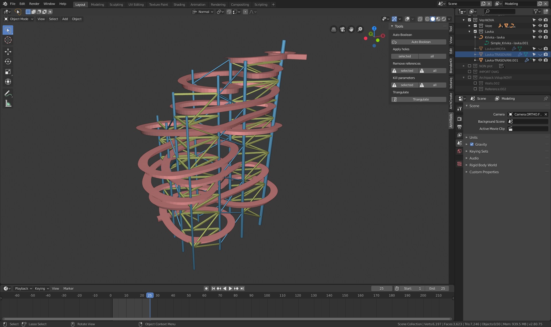
I need to make curved pathway. It will be quite high (55 meters) watchtower with pathway to top. This pathway should have same slope on whole its lenght.
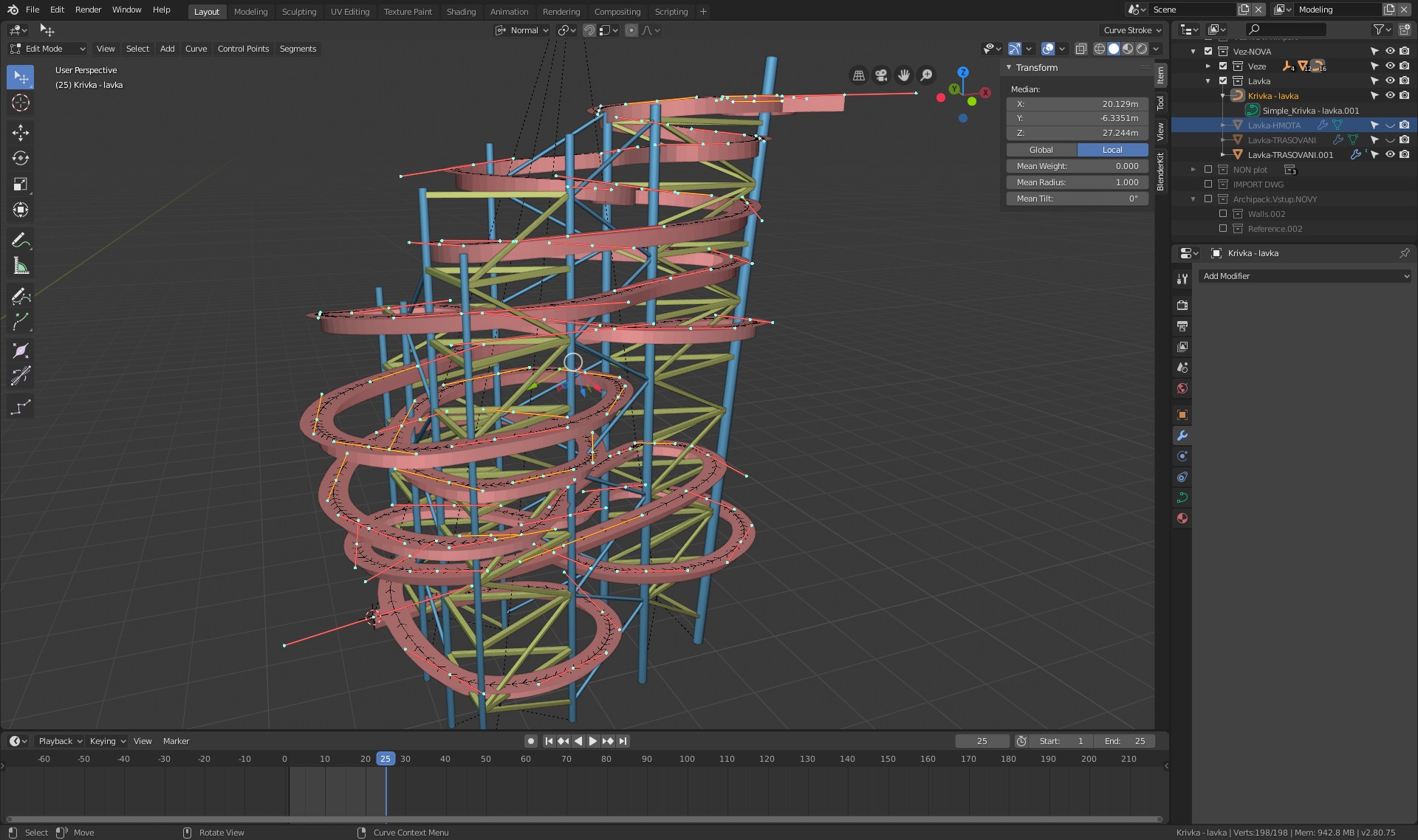
The way I do this now is to make whole curve rough shape. Then add 1m segment, array and deform it on the curve. When adding 1m segments in array modifier I can say how far is each bezier handle from start of curve and then I can put it on the right elevation to maintain right slope.
Problem is that I have like 70-100 handles on the project and it takes hours to do this by hand. I am making like 4th project like this and makes me crazy
Of course there is problem, that as the curve is totally random, every point is in different distance from each other, it could not be done by linear calculation of height.
Does anyone know other (some automated) solution how I can distribute handles only on their Z coordinates to maintain same slope on whole curve?
Some simpler solution would be huge help…
Instead of a curve modifier, you can use a Bevel Object determining a section profile.
Then, setting Twisting Method of curve to Z-up should be sufficient.
Well this does not work as when moving handles, it changes its lenght so changing slope. Or I missunderstood Your solution. But if U mean make slope from planes in some linear way, this does not work.
It has to take curve lenght into account and bassicaly add height to points bases on theirs distance from start of curve.
Well, it is not about the profile at all, but more the curve itself.
It does not mather for me, if it is curve modifier or bevel profile, but the sloping of the curve itself
I don’t understand. The way you describe your issue, you have too many control points to fix manually, correct?
So, say you want to fix a section of your curve. It has a fixed slope. If you put a plane inclined at exactly that angle under it, and shrinkwrap that section onto that plane, all the points should align nicely. That way you don’t need to manually keep track of any length, slope is set with a plane, curve points are simply projected onto it.
Or I indeed don’t understand at all what it is that you’re asking.
Well maybe I did put it not clear enough. The curve “should have” fixed slope but it has not. it is just estimated by me.
The problem is, there is no problem to fix slope on some handles or part of a curve. This is not what I am trying to acomplish.
I need to vercitally align all control points between 0 and 52,5m in Z direction only to make slope of 6% (rise over run - measured on whole curve). Slope of whole curve (not talking about some parts only) is indeed dependent on the position of control point and his distance from start. That defines the slope
So for instance curve is 875 m long and should rise 52,5m on this lenght = 6% slope.
I know start of curve, I know end of the curve and ending height. And also I already have its “top view shape”…BUT I cannot tell what elevation each control point (between start - end) should have.
Super easy to do if the curve is split into same lenght segments, but if control points are randomly in space and their distance is different on every segment, that is more complex task…
The solution should be:
Take control point and define its Z height based on distance from start. Input parameter here would be either “fixed slope+end elevation” (distribute control points on the Z) or “fixed slope+fixed lenght of curve” (changing ending elevation of curve). Then, if control point changes X/Y position and it also changes lenght of curve so Z height should be changed also to maintain same slope.
This would need be some script I think…But I cannot do that as cannot program anything Would be useful in designing architecture (roads, ramps, pathways,…).
If I did not make it clear, forget about it…anyway thanks for trying to help
I know about CAD software and I use Vectorworks and CADWork too. Just wanted to know if Blender is capable such thing because it has a lot of great features.
In CAD it is definitely harder to make such a thing quickly and see deformations of curve and array object in real time.
Maybe I could go to export curve. Edit heights of curve in CAD and import back to Blender.
Could work a little faster than my actual manual editing
Create a line in top view that is shaped like your path way but make it flat.
Create a second line, a straight line that slopes upwards in side view.
Make the second line at least as long as your whole path and then subdivide it a bunch of times.
Add a curve modifier to the secon line.
Use the first line as Object in the modifier.
Test which Deformation Axis is the correct one.
You now have a perfectly sloping line wriggleing its way upwards which you can use to extrude your path on or use some cross section as its bevel object in the Geometry section


 Would be useful in designing architecture (roads, ramps, pathways,…).