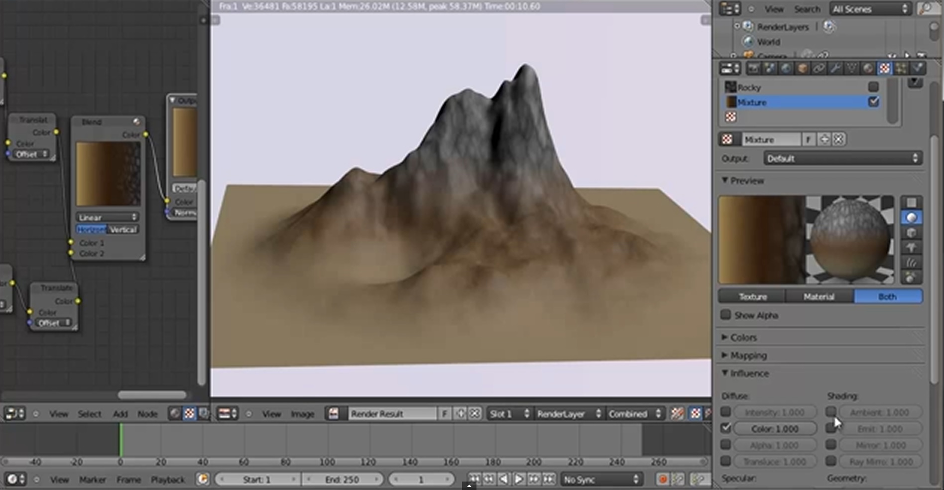
I remember you could make “height” based textures in blender internal to blend different materials by setting the mapping to z - z - z. However, I’m not sure how to do this in cycles.
In other words, what node setup would achieve a result similar to the image below?
An easy way to do that: Take your mountain or anything, in front orthographic view, unwrap it with “Project from View (Bounds)”. This way, the whole height of your object goes from 0 to 1 on the Y axis of the UV map. After that, you just need to get to that Y coordinate and to use it as a factor.
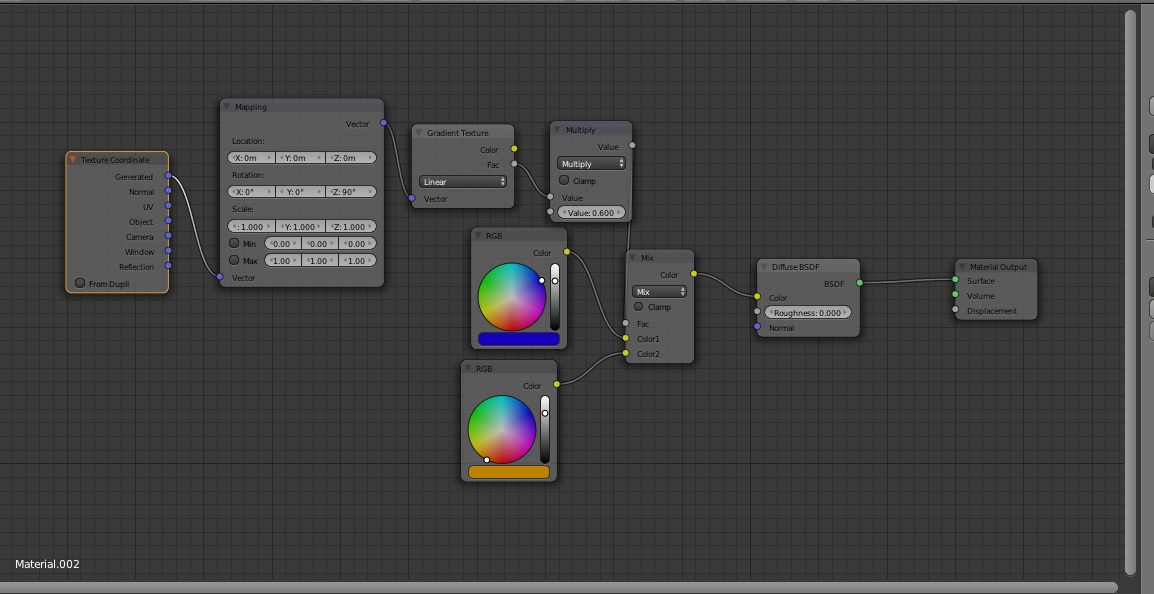
This is a quick example with 4 colors representing 4 materials (grass, dirt, rock, snow). You just need to replace the colors by materials (using Object coordinates or another UV map) and the Color Mix nodes by Mix Shader nodes.
The color ramps are here to set the limits in between the materials. Where and how sharp or how smooth.
The use of a rotated gradient texture (set to object coordinates) with the help of the mapping node should give you the same thing without wasting a UVmap slot.
You can go even further by using some vector math to create masks based on slope as well, which will greatly help the realism.
Hmm, do you have a link explaining how to achieve this? I googled around but I’m not sure how to use the vector math node. What would the node setup look like?
This is an example of how you can use the vector nodes to create a mask based on terrain slope, nodes that are not required if all you’re going to do is map a gradient texture to fade out based on the height of the geometry.
Anyway, with a combination of gradient texture mapping and this setup, you should be able to create some extremely realistic terrain.
I am coming back to this with a sphere shaped object and I can’t seem to get it to work. Does anyone have some tips on how I can get a spherical landscape to color map based upon height? I want the low areas to be blue and the higher areas to be white. I tried the various options on the Mapping node but it is still a hunt-and-peck mystery to me.
Thanks for the link I have always been afraid of that thread because of the number of posts. I tried to download the BLEND file but it has expired. I’m not sure that is what would work in this case however. That looked like a procedural planet. So the source for the height is in the noise texture. What I have is an already sculpted sphere with no associated height information other than the location of the vertices.
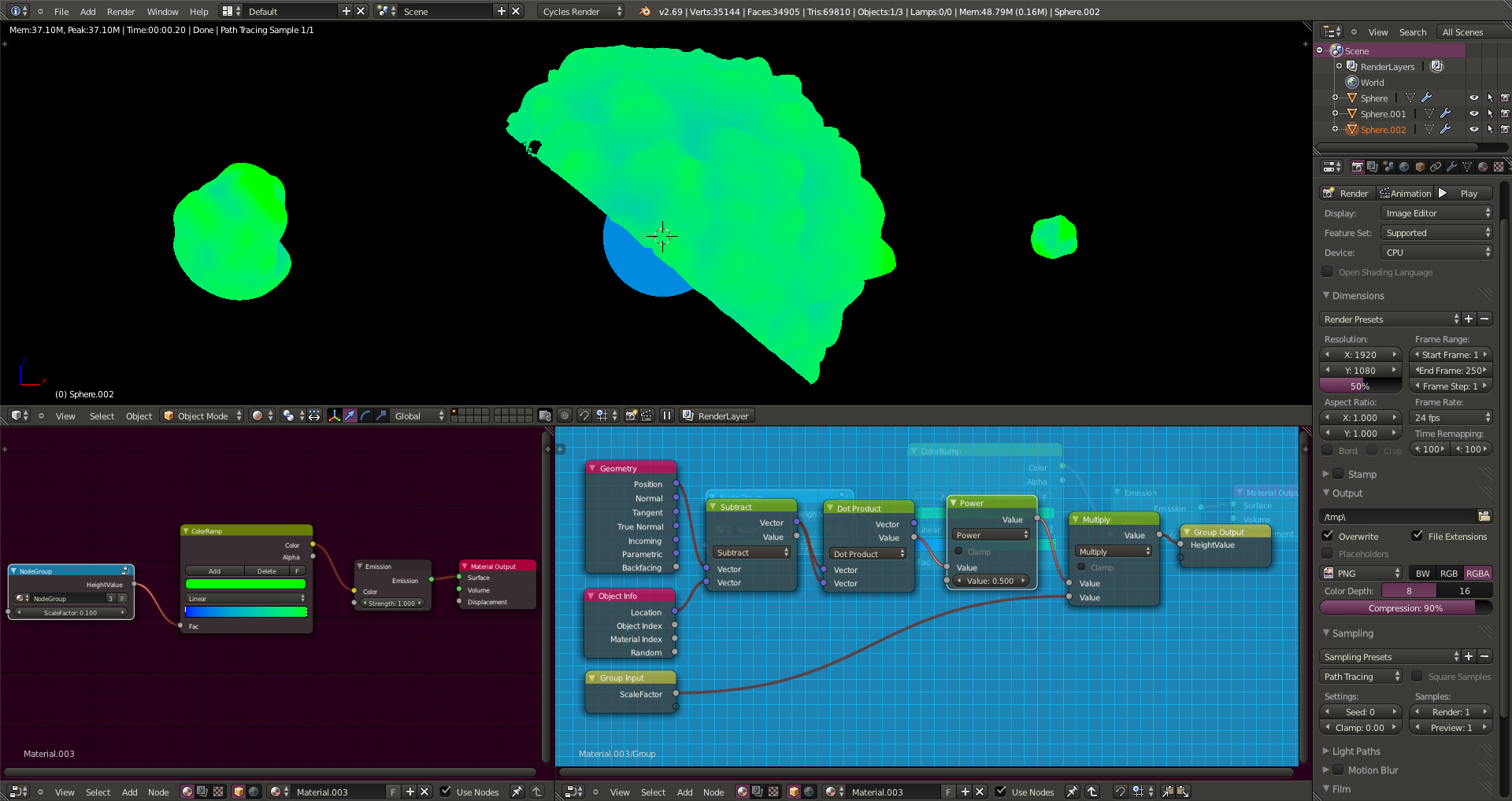
I guess I am looking for some way to measure how far a vertex is compared to the center/origin of the object. That should be a distance value that can plug into a color ramp.
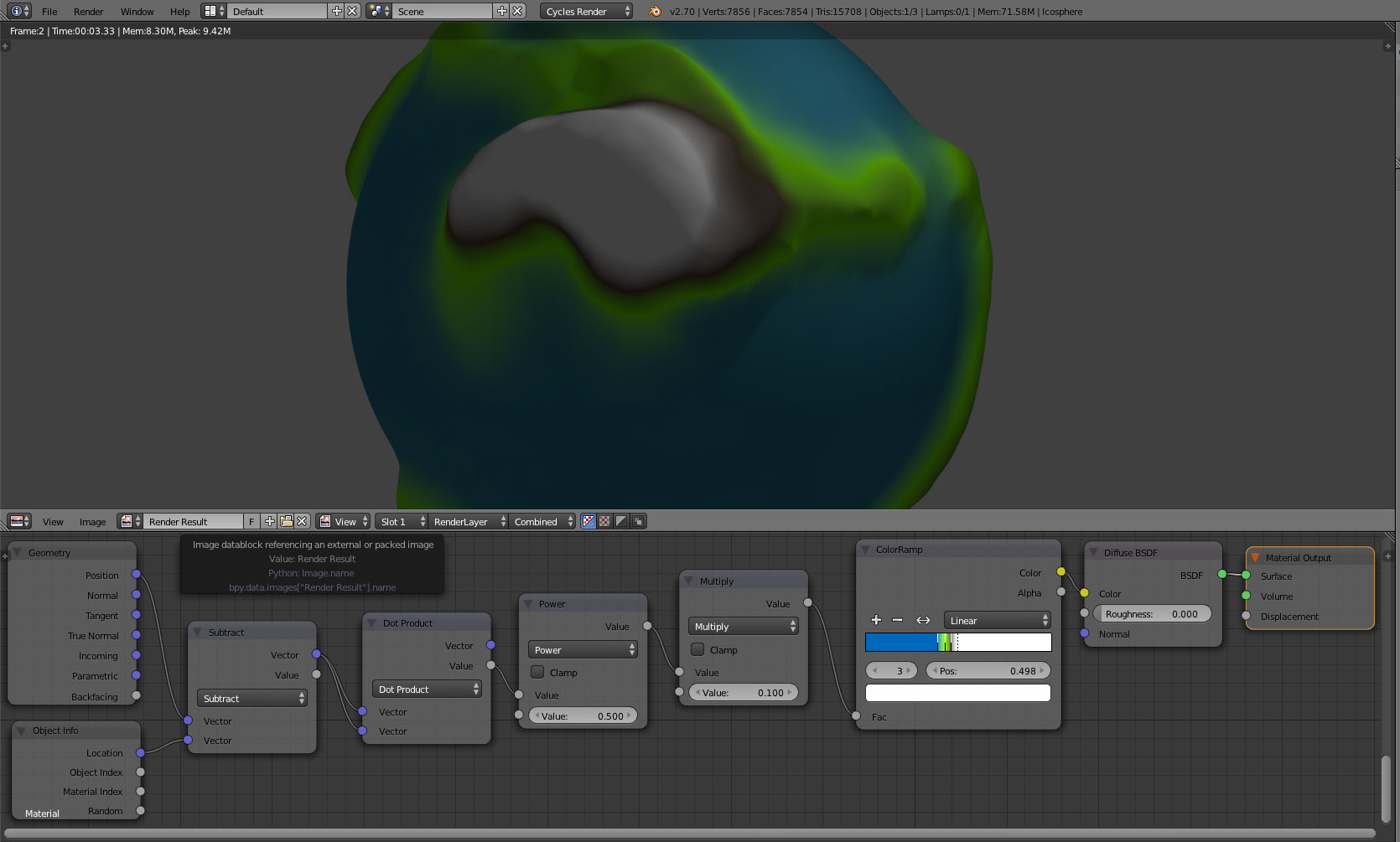
Thanks for the suggestion, I can’t seem to get a positive result, however. It seems like the result of the Dot Product is always 1.0 or greater and thus returns the color on the right side of the ramp.
Atom, you were right, that was done based on displacement texture i was referring to.
There is a file with 2 versions, one from anurag.k which works here. Only thing i can think of is Objects scale or that Object’s mesh is far from it’s origin. http://www.pasteall.org/blend/28349
The only change is the addition of the ‘power’ math operation. The nodegroup now gives the ‘real’ distance from origin. The problem is as eppo mentioned, the distance easily goes out of the range for the color ramp to work. This can be solved by adding a multiplication factor (the ‘radius’ of the object) to scale the value back into range. If only there was a way to get the ‘size’ of the object via a node
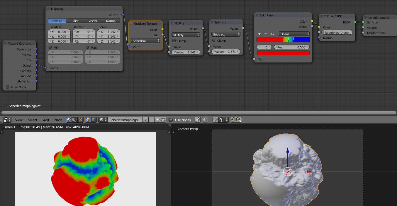
However the spherical gradient method is the best way to do it i guess, no vector math required
@jimmy: For some reason I could not get your spherical gradient setup to work on my geometry using Blender 2.70 official release.
@anurag.k: You setup does work in a very narrow color ramp range. It would be nice if there was a way to scale the color mapping so I could use the range more fully. I tried playing around with the Power and Multiply nodes that feed the color ramp but I can’t achieve a better scale.
I think power node is required because without it the value returned would be the square of the distance from origin. Ofcourse we can always adjust the range to our liking using curves but it would not be the ‘real’ distance right :P? The advantage with having real values is that we can easily adjust the min and max values in the node
EDIT:
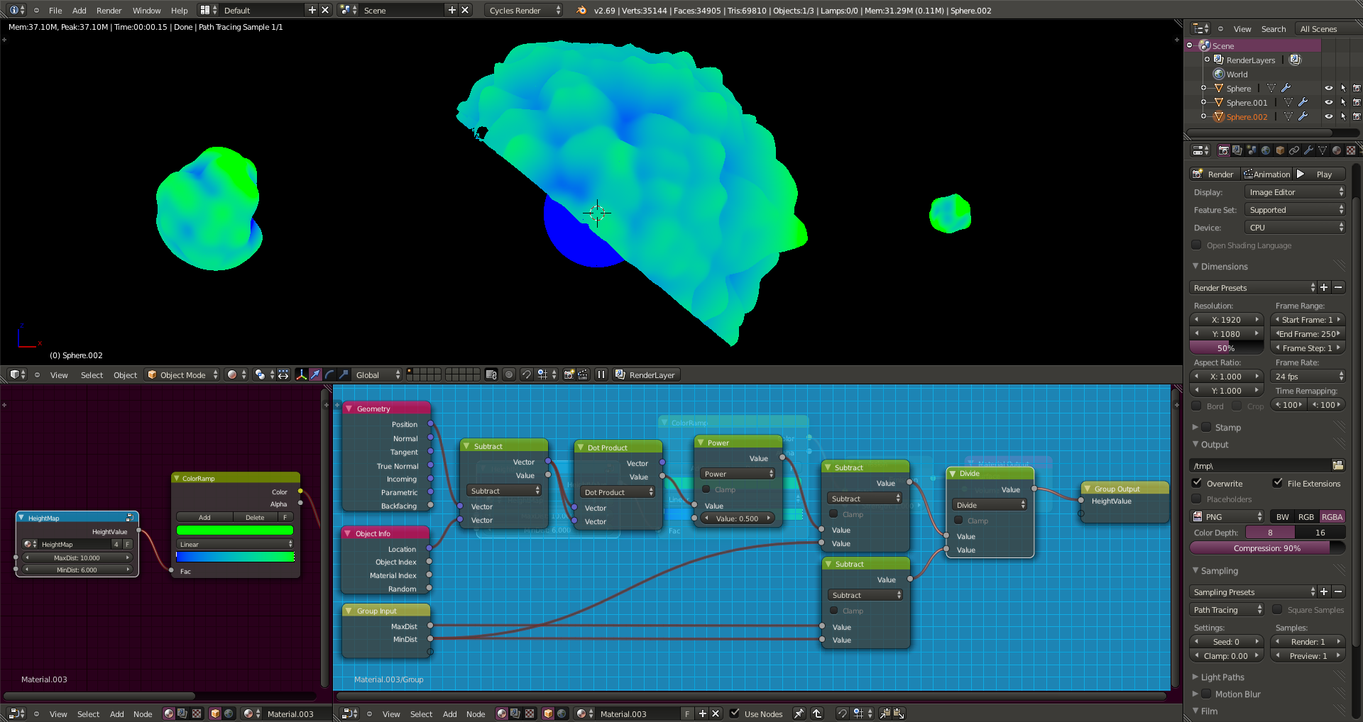
In case i was not clear, the min dist in the node is the value of distance(blender units) that the lower end of color ramp will correspond to and the max dist corresponds to the upper end of ramp. So we just plug in the size values for our required model.