Cycles Realistic Texturing HELP

Yeah, I had problems with the holes when I tried what I suggested. After quite a few attempts to make the Subsurf modifier behave, I totally re-built the rings. I got a better result in starting from the holes made from the back of an emerald.


It’s not perfect… (If I could find the idiot who made the handle not circular… errr… That’s me.) :smiley: …and there are Ngons. I know how to remove them but after my long fight with the Subsurf modifier and a second fight with that non-circular handle, I had a sudden attack of laziness. :wink:

And I agree with you, the emeralds are nice with the bevel I suggested.

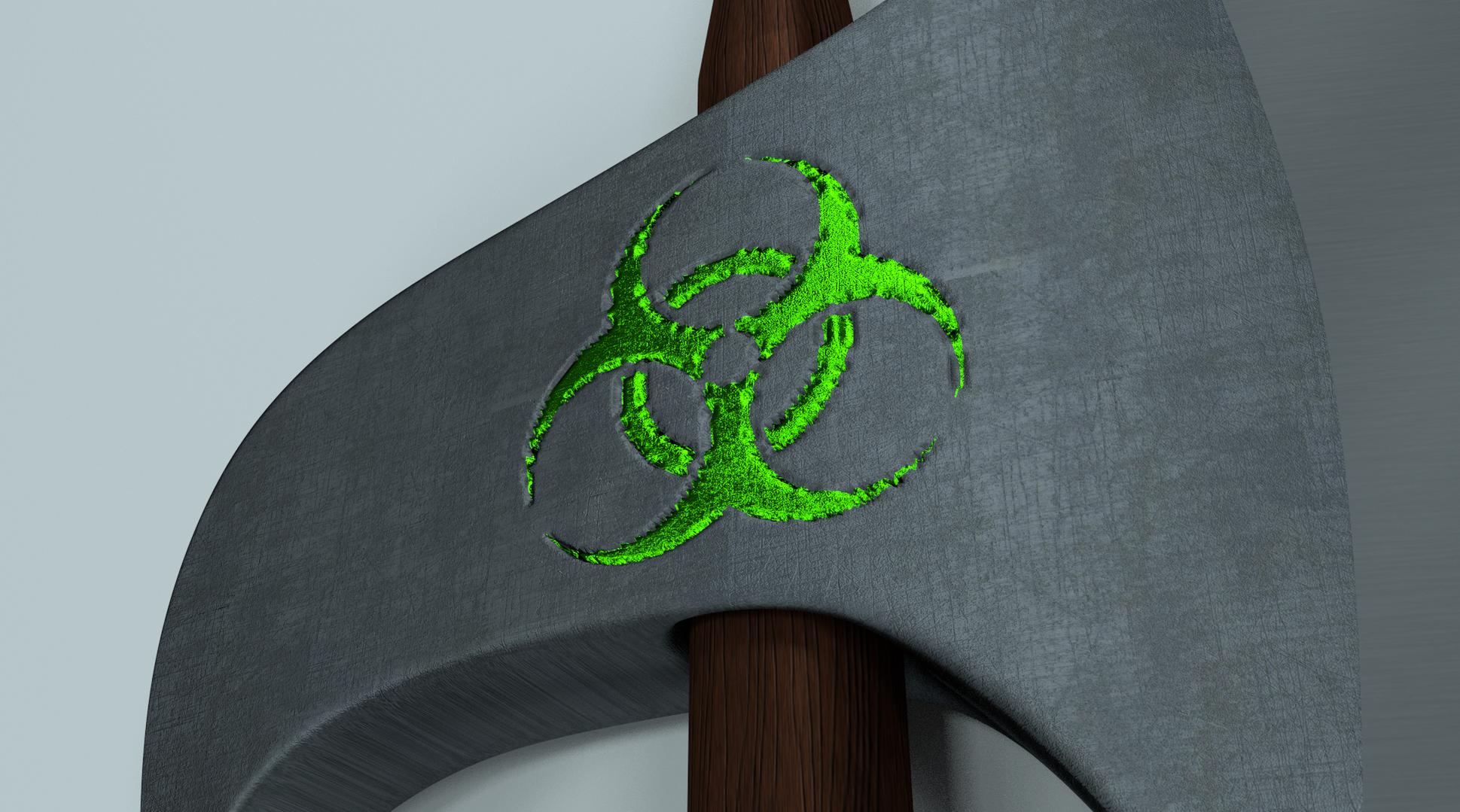
As for the groove around the symbol, it’s just a regular bump map… with another image while still keeping the same image as factor for the 2 materials. (Well, I tune it a bit to put the separation where I wanted.) The image for the bump map shows only the contour of the symbol and the width of the line extends outside and inside of the symbol. This way, the center of the groove is just below the border in between the 2 materials. Piece of cake! :wink:

Now, those electric lightnings… I can think of a few ways to animate them “by hand” but I’d still say “No thank you” to such a Godzilla-sized task. The easiest way to do it is (probably) like in the game, with a texture of lightnings on a fully transparent background on a dedicated mesh. You animate the texture offset to jump from place to place… et voilà! Another piece of cake.

Drawing the lightnings might not be so easy tho, and Cycles doesn’t work well with texture animations in the viewport. At least, it had great difficulties showing any animation last time I tried.

(I just checked and it appears to be working in Rendered mode… which is a huge progress!)

And my infinite knowledge comes from experience. You’ll understand when you’ll celebrate your first 1000th birthday. :eyebrowlift:

Okay! :slight_smile:
When I model another axe, another time, I will think better, do better, and all that from start which will make it much easier later, I won’t have all these problems I’m having now! :smiley:

“The image for the bump map shows only the contour of the symbol and the width of the line extends outside and inside of the symbol. This way, the center of the groove is just below the border in between the 2 materials. Piece of cake! ;)” Whaaaaaaaaaat? I get that you made or found another image of just the contour of the symbol, but then, did you mean that the contour, goes to the inside and the outside? it gets wider or something? I don’t really get what you mean. Here is a picture of the symbol, and a picture of just the contour of the symbol. (removed the inside of the symbol in photoshop, now that is a piece of cake! ;))


I used field blur - strength 11 at both in photoshop as well.
Is this what you meant making? It sounded much more complex when you said it so I guess it is much more complex! :slight_smile:

And about the lightning, I have heard about the transparent lightning before, sounds viable. (if you can say that? :O)
Eppo, your lightning looked really cool. But how do you grow Ivy or what you said? Is there any good youtube tutorial on this or is it easy to explain? I have another project going on for a few days, another weapon actually! I want it to have lightning at a place, it would look so awesome I think, it does in my head at least. :slight_smile:

Btw, how old are you guys? I bet you have used blender for +2 years as don’t know how much you know, I only know that you know much! Try to find out how old I am. :wink:

LOL You understood me despite my convoluted explanations. The images look correct. The way I did it with the GiMP (more or less): Select the symbol, enlarge the selection by a few pixels, fill the area, shrink the selection by the double of pixels that I enlarged it, delete the selection. A lot of blur. Done. So, yes, the contour must go outside and inside. When you imagine how and where this bump map will alter the surface, you must realize that it will create a groove just under the edge of the symbol, the same edge which is also the limit in between the green and the grey materials. I hope it’s clearer this way.

A good Ivy Generator tutorial, right on the topic: http://www.youtube.com/watch?v=UIwwuB0qGBo

As for my age… Let’s say that I have started with 8-bit computers in high school, in the days of the tape recorders and when 64 KB of RAM was the extreme luxury. It was the beginning of the computer revolution… 30 years ago. But I’ve started with Blender no longer than 6 or 7 years ago with version 2.48. I used it to create assets for an online game. I spent a long time hating the new 2.5 UI until I started playing with Cycles on GPU. Node trees speak to me. :wink:

You? I’m not sure that you’re old enough to buy (legally) alcohol in the USA. The fact that you post mostly on week-ends and holidays is what makes me believe so.

OK haha! :smiley:
I understand it better now, I do think I didn’t do exactly like you did, I only selected the symbol, decreased the selection by a few pixels and then deleted what was inside the contour, I never increased it outwards but that wouldn’t be hard to do. :slight_smile:
If I use a symbol that is black, but the background is transparent, it doesn’t seem to work the way it did with a white background, because now the whole area where the picture is, a big square on the axe head is filled with one color. Can you fix this any easy way? Because the great resolution pictures often got transparent backgrounds.

Before I asked here about the lightning effect, I Google it and I found a few videos about it, one of them where that one but to be sure about a great method of doing it I asked here so thanks! :slight_smile: Haven’t tried it yet but I will. You were actually older than I thought! Are you as good at modeling as you are with materials? I want to work with modeling for games when I grow up, I find it very interesting because I have been playing PC games for a long time with my friends. BTW, what online game did you create assets for? You did a pretty accurate guess of my age, I’m 14 years old and soon 15 (this summer).

Before I do the Ivy I would like to fix another thing on the model (I’m talking about the model that you never have seen but you will when it’s done ;)), lets say I got a cube, I split the cube in the middle and separate the two parts a little. I want the sides that are pointing towards each other to get a nice glow. The two walls which got a small gap between each other. After I made a material, for example the plasma material that @eppo mentioned, I would like to make the final adjustments to it in the compositor so I separate the two walls with the material from the cube, and put them in another layer. When I add blur and such and mix the two layers you can see the plasma material through the other walls of the cube instead of it showing up behind the walls if you understand me. How do I make it show up behind the other walls?

Think that is all I got to ask right now. :wink:

If your symbol is on a transparent background, just use the alpha channel as factor instead of the color. You can’t say for sure what color the background is… if you can’t see it. :smiley: Note that you may need to invert the value before to use it. (Transparent/black == 0 and solid/white == 1.) And, please, use a math to invert the value (1 minus the value) instead of a Color Invert node which also adds 2 hidden conversions on the noodle.

I am as surprised by your age as you are. You don’t speak “txt”, you make long sentences without awful spelling errors and you’re not afraid to make long posts. Keep on this way! :wink:

I used to do sculpties for Second Life. It’s just a very special kind of meshes with a lot of restrictions. But my main activity has always been scripting a.k.a. programming. Nowadays, I’m not so much in SL any more. I spend my time in Blender to make real meshes which can be imported directly now. I’ll certainly restart spending more time now that we have bump maps, specular maps and a lot of interesting stuff for the scripters on the horizon. Still, I’m not that good of a modeller. I’m good only with geometric stuff. Straight lines and precise curves which go well with my programmer’s mindset. I need to loosen up to become better with organic stuff.

Now, the glow. You don’t need to play with layers. It just makes things more complicate. Use a material index. Just for the fun, I split a cube…


As you guess, there is one material for the outside and a second one for the glowing inside. I didn’t split my object across layers. It wouldn’t have work any way because of the ton of modifiers in use on my poor little cube. :smiley: Instead, I activated the Material Index on the Layers tab (the Render tab for the older versions), gave an Index of 1 to my material and used it in the Compositor node tree.


And here is my reusable Glow node. (Not very reusable actually because of all the parameters that can’t be accessed from the outside.)

You start from the render layer, use the ID Mask to set the Index and separate virtually the matching material. You do what you need and, at the end, you add the effect over the render layer. Simple. :wink:

Using layers is only for whole objects.

Hey!
I have been thinking a lot about this, especially about the glow effect with material index since I don’t understand everything about it, will get back to that later.

I used a blurred contour on my old big axe but the result gets very bumpy(?).


I think the picture talks for its self… I have tried many times by removing the picture and done it over and over again but still same results. Does it need more blur? or does it need to thicker? (I mean the contour)
Here is the contour I have used:


Now for the glow…

As I mentioned I have thought a lot about this, while continuing working on my project that I hope to get finished by this weekend. The glow will be a finishing touch and a very important part of this project. I understood how to activate the material index in the render layers section, and that it is an important setting for materials. If I activate the index in the render layers tab, does it make so that it will render material index settings if you use that somewhere? Or does it like set material index to all materials used?

Well, that wasn’t the most important question, whats more important is what you gonna do next. The picture you posted of the node tree was a picture of a group right? I mean there is a group node in both ends of it but I have never worked with groups before so I’m not sure how it really works. You could had placed all that nodes outside the group and it would had worked all fine but you putted it in a group so that it would be much more organized? Or is grouping for other stuff more than organizing big node trees? (do you use any older version of blender? because my doesn’t look like yours.) How did you place your group in the composting node tree?

I divided the picture you posted in to 3 sections, which I will explain after.


RED = Pretty much unknown section, I see that you activate the material index here but you mix some image with black? What is that image and why do you mix it with black?

BLACK = This is the glowing effect if I’m not totally retarded (some blur and some nice fog glare effect). :wink:

BLUE = This is where you add the effect to the original image and then put the final result of this group in the output at the end in the group output node.

The red area need to look like that for this effect to work but I don’t really understand it. The black area is where I add the effect/s I want to add and the blue area is for completing the group for a result, If I got all this right.

Damn, all my posts get so long…
Guess it is because I don’t post every day exactly, I wait until I have gathered some information so I’m not totally gone when I reply (or am I? :)).

Thanks! :wink:

Drop the tea spoon and take a shovel to add some blur to your contour! :smiley:

Right now, your image is very smooth, not really blurry. Just don’t stop adding some blur until the image is painful to look at because your eyes can’t focus any more. :wink: (And I’m serious despite the smileys.)

The image with the green background is effectively a snapshot of a group as seen in Blender 2.67+. (I update almost very week with the last version available from the build bot so I lost track of when the change occurred.) It’s green because of the color I gave to my group header. For the rest, that’s how node groups are edited in Blender nowadays: Full screen… Well, within the limits of the Node Editor.

When I open the Node Editor, it looks like this:


Very straightforward. And yes, I grouped the nodes for the glow effect so that the whole mess doesn’t hide the backdrop. Besides, since it’s a group, I can append it easily into another blend file. Here are the 2 major reasons to group nodes: To limit the clutter and to reuse.

As for creating groups, it’s the same than with objects. You select what you want to group and [CTRL G]. The presentation is different from the older versions of Blender but the basics are the same. All your grouped nodes in the middle and the sockets for the group on one or both sides. What is really new is that you now need the [N] panel of the Node Editor to rename, re-order and remove your group sockets. In the older versions, these commands are available directly within a giant node which appears when you [TAB] into a group.


(I had to re-install a version 2.66… and then a version 2.65… because the new Node Editor is already in 2.66+. Luckily, I don’t really install Blender on my Linux box.)

Any way… You guessed right. The nodes circled in black are the glow effect and the ones circled in blue add it to the render.

Now, the red part. It’s a bit confusing because the names aren’t consistent. You plug the “IndexMA” (Material Index) into the “ID value” of the “ID Mask” node and it spit out some “Alpha”. The “Index” is actually the material you’re interested to work with. (I’m glad I found a tutorial about this and that I didn’t have to guess all this by myself.) Still, I figured out on my own how it works. Let’s see if I can explain it.

When you use a material index, Blender creates an alpha mask for all the indexes used by the materials. (You can have as many indexes as you want or give the same index to several materials.) Such an alpha mask indicates where a material matching the corresponding index is in direct line of view of the camera.

Thanks to this mask, you can replace everything from the original image (usually the render layer) which doesn’t match the material index with black. (That’s what the Mix node does.) You can then manipulate this new (virtual) image to add any effect you want to it and, in the end, you add this image on top of the original image. Here, adding and the black color are important because black equals zero. So, the parts which aren’t affected by the effects and remain black won’t change anything when added to the original image. (Anything plus zero equals the same thing.)

I hope everything is clearer now, Little Grasshopper. :wink: (The correct answer is “Yes, Sensei.”)

Oh, well, lets add some blur!
adding blur
Still bad…
adding more blur
Better, but very small difference.
adding moore blur
Wtf? Is this it?
ADDING TONS OF BLUR
WHAAAT? really? I have done something wrong! :smiley: (at this point, the picture is almost invisible in Photoshop cause it got so much blur)

The picture:


It is so blurred, that the results get awful, in the way that blender can’t see the contour everywhere anymore, look:


(I removed the green color just because it is easier to see now how bumpy it looks)
Do I need more blur? Just kidding, what do you think I have done wrong? :smiley: It gotta be something with my image, right?

I’m starting to understand the glow much better now, I just gotta keep reading the “red” part some more! :smiley:
I tried, but I don’t get any difference from the look as it was before I made the effect. I copied all your settings to try get it work so I could experiment with the settings, but the end result looks just like the results before I even changed anything (I also noticed that I needed to update my blender, used to online games which updates them self :smiley: I still had blender 2.66 where you could TAB into a group and edit everything in it from there). Here is a picture of my node tree outside the group:


(I cover the rendered image with red because I don’t want to reveal my project yet!)

I can’t post an image of the inside of the group in this post as you only can post 3 images/post, will make another post immediately and just post that picture there.

EDIT: Oh wait, forgot a question, as you can see I have put textures on the head of the axe. How do I unwrap the head, so that both the symbol, and the texture gets right? I know, that you know, how to fix this! :wink:

Here it is (the glow group):


As you can see, there are some black windows where it is supposed to show the effect which that specific node is making to the image. Don’t know why it is clean black, I will let you solve this!

Thanks man! :wink:

You can get nice blurred image out of blender compositing - take as an input your sharp outline image, feed it to the blur node at the maximum value you want to be blurred, put it into color mix where this is mixed wit the blur again, just a less value. Repeat some 6 times and you get pretty nice blurred thing to use. Or do the same in PS. And the last thing - see this horizontal groove - you need some pixels of 100% transparent border. Or black, if that is a mask.

There’s a tiny difference in between “my” glow and “yours”. Look at my Glare node. Threshold: 0 (zero). :eyebrowlift: That will make a big difference. And you must not forget to set the “Pass Index” (another new name for the Material Index) for the glowing material to 1. (Material tab, Settings panel.) Otherwise, Blender sees nothing matching this index… hence the black images.

Now, the blur. I don’t know what kind of blur Photoshop uses but I used Gaussian Blur in the GiMP. So, Eppo’s idea to use Blender to do the blur is an idea to remember.

I re-did a bit my textures to get rid of some “big pixels” in the curves.


There are still some fatty pixels with their belly sticking out of the curves and the groove is way too wide but that’s much better than what you did any way. :wink:

Here is my new version with all textures packed inside: axe_5.blend (2.22 MB)

(Gah! 2.2 MB. My file needs to be put on a diet!) Note that I used alpha as factor in my node tree… and other oddities.

Will try this out, seems like pretty easy mistakes from me. Before that I just want to add, that you missed my last question that I edited right after I posted it.

Here: “as you can see I have put textures on the head of the axe. How do I unwrap the head, so that both the symbol, and the texture gets right? I know, that you know, how to fix this! ;)”

I always got lots of questions, with lots of text in between. I completely understand if it can be a bit messy! :wink:
You really know everything, because you answer so damn fast! :smiley:

And great tip eppo, will put that on my mind!
Good job guys!

EDIT: In a material node tree, there is only one displacement output, but I want to use two different bump maps for two different materials in that material if that makes sense. Can you mix them with a math node? Because I have tried doing that, with some different kind of operations but I can’t find anyone that works like I want it to! (only tried a few) :smiley:

Yep! I totally missed the last question…

I tried a lot of things to unwrap the head and in the end, I made a butterfly… :smiley:


I used the regular unwrap with seams. I added a seam all around the head, along the mirror line, except for the faces “inside”, around the handle and at the tip on the dark side. I created separated islands for these “inner” faces with a seam around the holes and only on one side of the cylinders, and another one for the dark tip (as you can see with the red rectangle on left of the snapshot).

I unwrapped each half of the head separately with the regular Unwrap set to “Conformal” in the [T] panel. Then you have some hard work. You must rotate the 2 islands in opposite directions and move them to make the central faces match. The better you do it, the more symmetrical the result will be. The final touch is to scale and move the 2 islands to position the symbol where you want.

After all this, don’t forget to also unwrap the “leftovers”. (Don’t worry much about the difference of scale since these parts are seldom visible.)

Now, 2 materials and 2 bump maps into one. Easy! :wink:


Here I added a simple stretched noise as bump map for the steel.

The 2 materials are chosen according to a factor. You just need to re-use this factor to choose the matching bump map. Since bump maps are more or less regular images, a Color Mix will do the trick. Pull a noodle to bring the factor. Done!

You can also manipulate the factor along the noodle like I did here. I used the image of the symbol as factor to separate the 2 materials but the groove extends on both sides of the limit. I needed the new bump map to leave the symbol and the groove untouched. I just added the 2 factors. Here, the image of the symbol and the image of the groove. I use the alpha channels but it would work with regular B&W images as long as they are the same: white drawing on black background (like the alpha channel) or the other way around.

We have a special case here but, if the factor for the 2 bump maps matches the one for the 2 materials, you can as well use Bump nodes to manipulate the normals of your shaders so that the factor to choose the materials will also apply to the bump maps. In this case, nothing to plug into the Displacement socket since modifying the normals is what a bump map does.

Damn, when I go into advanced posting when I want to post it says that I need to reload the page and before it said that what I wrote got saved but it’s not…

I will try to do this fast then.

I made another file to test the glow effect, here is some pictures:


Index set to 0.


Index set to 1.


Everything disabled/muted, it looks just as it looked when index was set to 1.

Yesterday when I made this file, I got other results when index was set to one, then there were small black stripes all over the screen, pretty cool, don’t know why I didn’t get same result now because I remade the effect as nothing showed up when I opened the file. And it only looks like my orange one is having some light, the other ones seem so off? Anyways, you can see the property tab to the right and you can see that material index is enabled. BTW, what does the “clamp” check box do?

Thanks for the tip with my axe, finally got it working, it is just the 2 bump maps in 1 thing I don’t understand. What made my axe head look ugly was because I used displacement modifier instead of bump map, forgot that but saw that when I looked into your file. Unwrap worked fine by using snap with Ctrl in the image editor, now it is completely symmetrical! The only thing left, is the bump map as I mentioned. When I mix the 2 bump maps just like you have done, I get weird results. Will post a node tree and maybe and image in the next post.

Thanks!

Check this out:


This is how the node tree looks like when I use two bump maps.


Result: Weird.


Result with only one bump map: Symbol looks like it should, but now there is no bump on the other texture of course.

Hope you see what the problem is as always! :wink:

You missed a tiny bit of sentence in post #89.

Instead, I activated the Material Index on the Layers tab (…), gave an Index of 1 to my material and used it in the Compositor node tree.

Look over there:


That “Pass Index” (Another name!) is the material index. It’s an arbitrary number set to zero by default.

If you don’t change it here for each material that you want to affect, any value that you might use in the Compositor has no effect… Except the default value of zero which means “Dear Blender, apply my effect to everything”. :eyebrowlift2:

Now, the 2 displacements in one. No can do! Well, you can… Either if you mix the 2 bump maps by yourself in a graphics software, or if you use 2 Displace modifiers. In the first case, any change that you might want to do means to redo the whole bump map. In the second case, you don’t have any fine control as to where the bump maps apply. Especially, you can’t use an image as factor to mix them. The Displace modifier knows nothing more precise than vertex groups… and that’s not really precise!

For the little displacements that you want to do, I think that a simulated bump map is more than enough.

If you really insist on using a Displace modifier, you can use it to carve the groove around the symbol, and still use a simulated bump map for the grain of the steel. You just need to replace the bump map for the groove with a flat color in my node tree. Simple… :smiley:

I can see a lot of things in your node tree…

Not all the textures have UV coordinates. Besides, you must pay attention to what coordinates you provide. The Mapping node used for the groove bump map prevents the repetition of the texture. You don’t want that for the steel grain.

Last, it looks like you’re trying to use the alpha channel of a JPEG image. Good luck with that! :wink:

Besides, using alpha works for me, because I made my bump maps with an alpha channel. Did you too? :eyebrowlift2:

Oh, just that sentence I remember that I didn’t completely understand it, thought you were just telling me that I need to set material index to 1 in composite and activate it in the render layer tab, will try this but will be gone soon and come back tomorrow for a small boat trip.

Anyways, for the bump map, If I understand you right you are telling me that it is much smarter to use a bump map instead of displacement map, and I also think so but you maybe misunderstood what I meant because I wanna do exactly like you did with your two bump maps, I don’t want to use any displacement at all, my problem is that it doesn’t show up like it should. As you can see, it got weird when I mixed the two bump maps. Maybe I misunderstood you know when I think you misunderstood me, but I guess I will find out! :wink:

EDIT: Whops, didn’t see you posted two times, only got one mail and this is on the next page! :smiley:
Will check that out as it looks like that is the answer I’m looking for!

I wouldn’t say that using only bump maps is smarter… but that using a Displace modifier is a bit overkill.

For the rest, let’s wait and see at your return.

In the meantime, I found something to celebrate…


For you, dear followers and visitors of this thread, so that you didn’t come for nothing:

Forum 100.blend (991 KB) =^_^=

Okay!
For the axe, do I need to put the image texture that is going to be all over the axe head, in a texture coordinate or how does it place the texture if I don’t? Does it automatically use the UV unwrap for the symbol? If I need to use a texture coordinate here, how do I then unwrap the head so that it got two different unwraps? One for the symbol and one for the other texture. Forgot about the image alpha channel and such, but It works if I just change it to the image output instead of the alpha, right?

This is how my axe node tree and rendered image looks like right now:


[ATTACH=CONFIG]238862[/ATTACH]
[ATTACH=CONFIG]238863[/ATTACH]
Bump on the texture works as I see it, the biggest problem is that the bump for the symbol makes the whole symbol go in instead of just the contour.

Now for the glow effect, YES! IT WORKS! :smiley:
Thanks to your brilliant file, I understood how index masks, index passes and all that works. I saw you got two different glows, one for the “#100” and one for the “=^_^=”. The pass index on the “#100” was set to one, and then in the composite node tree you used ID mask “1”. The other glow, had pass index set to two, and then in the composite node tree you used ID mask “2”. I understand that you can have like 10 materials on an object, but then apply different effects to each one of them by masking out that specific area using pass index and an ID Mask to mask it out. Everything got much clearer now! :slight_smile:

Here is a picture of the result:


I didn’t use much of the glow effect I made, because it didn’t fit in to this picture. This file was mainly to get things working, now I will try to do this effect with my real project again which I were working on before. :slight_smile:

Thanks for all the help, it has helped me so much this far!

EDIT: Now I know how to use different UV maps, you make different UV maps in the object data tab, then instead of using a default texture coordinate node, you use an attribute node and write the name of the UV map there, and then put the vector output into the mapping vector input or straight into the image texture input. I learned this while I watched a video on how to render objects in wire frame.