Thanks! Well, I think it is! It allows for some cool things which are otherwise impossible.
Thank you describing your finding related to spectral rendering in Cycles.
Still I don’t understand how you create the ‘wavelength’ controller? Can you share a .blend file using this nodes?
You could supplement “real” spectral reflectance curves with generated curves. This is a technique called “reflectance recovery” and several methods have created over the last 20-30 years. The python library Colour has a few: https://colour.readthedocs.io/en/latest/colour.recovery.html
Scott Burns also has a matlab implementation, and an excel spreadsheet implementation:
http://scottburns.us/reflectance-curves-from-srgb/
Keep in mind these methods are SLOW (which might be ok for a renderer), and the curves are “natural” to the extent that they are smooth, but have no other bearing to real materials. However I’ve been having some success with a different strategy: generated spectral reflectance curves for just the primaries; R, G, and B. Separately. Now whenever you want to convert an RGB triplet you can upsample each component separately by mutiplying the component against the primary’s reflectance curve Then, add up the 3 spectral power distributions (SPD) and do your compositing math: multiply, average, add, weighted geometric mean, etc, with another upsampled RGB. SPD. Then convert from SPD back to XYZ back to RGB and you’re done
2 Likes
@briend thank you for those links, I think that is exactly what I was looking for. I’ve gotten a bit better of an understanding of the topic now, and I feel it is possible to implement such transformations in Cycles nodes, but it certainly isn’t trivial. The biggest thing slowing down this workflow is the very long feedback loop. In order to iterate on an idea, you must make the material or scene changes, render out X frames depending on the spectral resolution you want, open those frames in photoshop, run a PS action, then look at the result.
I considered doing the same technique as you suggested, to create suitable curves for the sRGB primaries, then simply use the RGB factor as a contribution weight of the spectrum, and I do think this is sufficient for my purpose. The spectral information is lost when converted to RGB, so a smooth representation of each primary would at least allow images to be utilised in this workflow, and allow for progressive enhancement where it is required (such as in glass, light source spectrums, spectral interference patterns etc).
Do you know of any good resources for how to create suitable sRGB primary spectra? I tried to do it by eye with very little luck, if you’ve managed to implement it I would love to hear about it.
1 Like
I’m using these sRGB spectral primaries:
These came straight from the excel spreadsheet from Scott Burns site:
http://scottburns.us/wp-content/uploads/2015/04/reflectance-from-sRGB.xlsx
But I have tried spectral primaries from the Meng2015 method and they seem to work, too:
These methods all fall apart for wider color gamuts; Rec 2020 is impossible since the primaries in that color space are single wavelengths. I think if you remove the constraint that reflectance must be <= to 1.0, you can use Scott’s excel spreadsheet to generate curves for wider gamuts like Adobe RGB. I’m not sure if this is a problem, since >1 it is no longer a reflectance curve as far as I know, but it doesn’t seem totally absurd. It makes sense that you can’t generate natural reflectance curves for any x,y chromaticities that are outside the Pointer gamut, since by definition they would be “unnatural”
1 Like
Thank you! I’ll see what I can do with these, if I get anything useful I’ll post it here.
Good luck! Oh, if you use Meng, that method uses the E illuminant, which is totally flat. I guess that might be more convenient, because it seems like you’d just skip a step. Well, if you wanted an E whitepoint, I suppose. So you’d probably transform from E to D65 anyway using an adaptation method like bradford. I don’t know if pre-baking the illuminant into the spectral primaries is less complicated than doing the bradford. . . But this article might help:
http://www.brucelindbloom.com/index.html?Eqn_Spect_to_XYZ.html
and bradford adapation from E->D65:
http://www.brucelindbloom.com/index.html?Eqn_Spect_to_XYZ.html
But I would just use color math library like colour for that 
A graphics driver update has just killed blender for me… Oh well.
Currently the blender scene is based on an E whitepoint (I guess, since each frame is B/W where 1 is some reference intensity of that frequency), then in the photoshop action (which still needs work) I’m attempting to go from E to D65, but photoshop’s colour management is really getting in the way, so I’m considering other ways I can do the post-processing, but haven’t come across any perfect fit yet.
As for baking the illuminant into the sRGB primaries, yes, I would have to do so, I think, as sRGB uses D65.
I wish I could just use a colour math library, but I’m not familar enough with Blender and Python to get in and do that at this stage.
edit to remove bunk info ![]()
I’m defining the spectra of the light sources, too, but surely the sRGB values would need to be un-D65-ed?
I think the concept I’m trying to do and what you have in your mind might be slightly different - in the scene I have, I define the spectral intensity of every light source (so, for example, I could have a D65 standard light source, a flourescent light, and a pure frequency light source in the same scene) and I define all materials in terms of how they behave with that specific wavelength.
This means I can render the entire scene with respect to a particular wavelength (and output a greyscale image), and do that for all the wavelengths I need, before going into PS and then doing the standard illuminant correction (still haven’t quite wrapped my head around if I need to do this or not) and applying a response function for human vision of each wavelength.
That’s where my understanding starts to break down, since the human vision response curve for each frequency changes based on the illuminant…
I think I need to take into account the illuminant which resulted in the sRGB image (which is D65), but not necessarily my own scene, as the spectra will do their own things with funky light sources.
Ok yeah I’m getting a bit screwed up haha. So I guess it probably doesn’t matter if you use illuminant E to create the spectral reflectance primaries and just stick with that the whole way through. That would be nice so you could use the Meng method. The trick would be… say you selected sRGB green 0, 1, 0 for a green ball. . . BEFORE you upsample that to the (Meng) spectral primaries you would want to shift the color via bradford from D65 to E. so sRGB → XYZ → XYZ(E) → RGB → Spectral
So now the green ball has a good natural reflectance curve. You shine some funky light source on it and get your ~30 layers in photoshop. At this point you have spectral data represented as greyscale. So what you are probably thinking is you need to convert all these layers to one XYZ layer using the CIE color matching functions. You could use this function:
colour.spectral_to_XYZ
I have no idea how you could do that with photoshop layers though. But after you do that now you have one layer and each pixel is XYZ data. At this point you could use this handy function:
colour.XYZ_to_sRGB
and you’d specify the source illuminant as “E”. Bingo you’re image is now sRGB/D65.
I’m still not sure how you are taking the photoshop layers and using “add” to combine all the greyscale wavelength emission data. What are you multiplying the layer against?
oof a bunch of my earlier posts are hidden now as spam. . . maybe I can’t link to sites so much
My early posts also contained links, and I think they are automatically removed for new users, as it is assumed to be a spam bot.
You’ve got the process down to a point. It seems like that transformation process sounds about right, to go from sRGB to illuminant-independent spectrum.
Exactly. The photoshop is the bit that is messing me up too. I’m multiplying each greyscale ‘frequency’ image by it’s human-vision appearance colour, then adding all of them together. There’s just so many things that goes into calculating the colour (in any colour space) of a particular frequency. Photoshop doesn’t make this easy, either, because even in an XYZ document, the colour picker is in some other RGB space.
I’m thinking I’ll need to just take the dive and learn enough python and that colour library to do what I want. I’m not excited about learning how to interpret EXR images in it though…
I’m so happy to find someone I can talk with on an equal level about this, so many people I’ve talked to regarding this are either way over my head, or are trying to oversimplify it.
Ah, I see. Yeah that’s not going to work quite right without accounting for the LMS cone reponse differences ![]()
Maybe look at OpenImageIO for reading exr. Or, and I have no idea how cycles workflow works, but can you access the raw data without any file format, before the data goes into files? Like arrays of pixels? That would be ideal I think.
Yeah it’s nice to find someone trying to do the same thing I am but in a totally different program. Maybe we can both learn something, or get equally screwed up and implement something completely broken ![]()
That is something I haven’t studied at all yet, but it seems like that might be the shortest route to a working solution, if not the ideal solution. I think that’s where the issues I’m having now (odd/strangely weighted colours in the final result) must be coming from.
I would love to be able to get into Cycles data, but I don’t know enough about it and from advice I got from someone more experienced, it isn’t that easy to get access to that data, as lovely as it would be. I might be able to run a python script on the render result though…![]()
I’m giving us a 50/50 chance of either option, haha!
I managed to figure out how to do what I was intending to do in Photoshop, by using the scripting capabilities in JavaScript. I found an xyY => CIE RGB function written in JS and I wrote a function for wavelength to xyY. It is much closer than I’ve gotten before without any manual adjustments, but I do feel like maybe I’m forgetting one white-point correction somewhere. At this stage I am happy to just correct the RGB channels linearly, since the relationship between the channels is now pretty much perfect. Here’s a test from tonight:
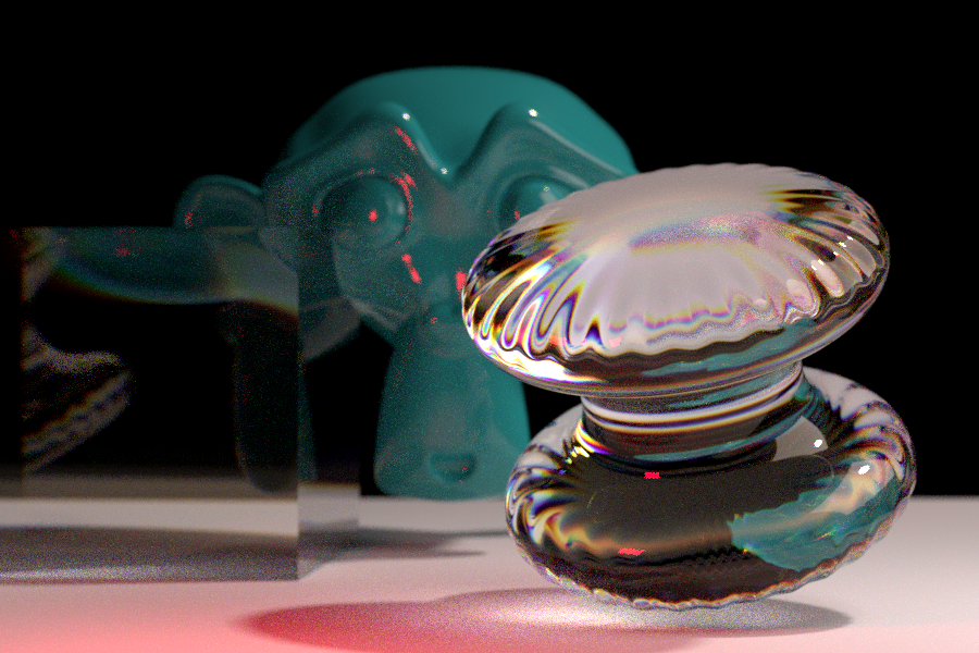
Bonus: this allows for selective sampling of specific frequencies. As the red light is only visible in a single frequency, I could re-render just that image with much higher samples to get a cleaner result.
Next thing to do is to get an RGB => spectrum node group, then this workflow might actually be usable! It would allow images to be used in conjunction with custom spectral materials. It seems like @briend’s comments might help me with that one!
5 Likes
Awesome! Pretty sure that should be equivalent to XYZ → RGB and much simpler than what I was imaging, which would involve cloning the layers a couple times and doing each X, Y, Z on separate groups from 30+ layers and then summing them all and then… convincing photoshop to believe the RGB greyscale data is actually XYZ data…
I don’t think you are missing one, well not yet. I think if you setup a object with a flat reflectance curve like all 0.5, 0.5, etc in the scene, and defined a lightsource with the D65 power curve. … do all your rendering and conversions in photoshop. . . now use the color picker and the RGB from the object should be achromatic like (0.5, 0.5, 0.5) or (0.9, 0.9, 0.9), etc. If there is a color tint then I think something is wrong.
So maybe take the D65-baked sRGB primaries that I linked to earlier in my code (or make them w/ Scott Burn’s excel doc) and test that out with a green (0, 1, 0) object, etc, and see if the colorpicker shows it is still the same green (w/ perhaps a lower brightness). If that all works then you only need to worry about whitepoint conversions if you decide to use the Meng E-weighted primaries or some other illuminant/white point.
Very cool! I’m glad I could help a bit. Once you get all that working you should check out OpenColorIO and filmic blender made by Troy Sobotka. I’m guessing you or Photoshop are clipping the RGB to 0-1 right now (upon display). But if you shape the RGB data in a different way you can keep the scene-referred values >1.0 and view them in a more natural way.
I think you could create a special ICC profile from filmic blender. google filmic blender and go to opencolor io’s website and they mention photoshop compatibility (although the link is 404, I think the right path is userguide/baking_luts.html). Troy provides a config for blender (filmic blender) with the sRGB LUT already setup and ready to go, but no ICC profile.
1 Like
Yeah, I thought I could assume everything being ‘flat’ would result in even channels, but I guess I need a D65 light source to get that. I’m happy with where things are at.
I’ve converted your primaries into a node group which allows usage of rgb colour data, and it works reasonably well but I think there’s something playing up with my colour management at the end, since the blues especially are quite dull. It could be a gamma or colour profile issue.
I am currently doing a ‘dumb’ clip of the HDR data when exporting from PS to PNG for the preview images, but I could export HDR, then import it back into blender to run it through filmic if I wanted to. I am fairly comfortable working with HDR data so I’m not too concerned about which particular method I use to do HDR>SDR mapping. Filmic is wonderful, I’m so glad it got added.
Summary and some more test images coming soon! Sadly I don’t currently have any way of doing fluorescence, other than rendering two sets of images and combining them after. That’ll be next.
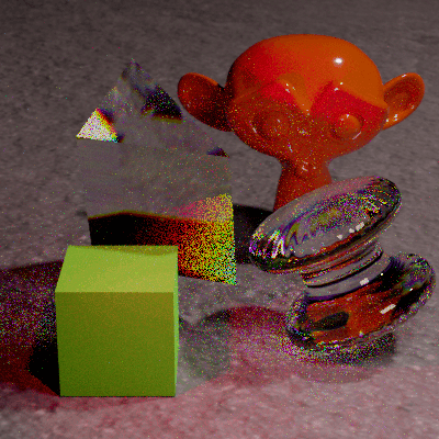
This image is using my RGB>Spectrum node group with pure red on the Suzanne, and pure green on the cube. I’ve converted it to sRGB from CIE RGB but it doesn’t quite seem perfect. That could be due to the light sources I am using, which are neither D65 or E.
The floor is using an image texture for the colour, as well as a roughness and normal map.
3 Likes
Woah, looking better!
The reflection from the object will be the light source multiplied by the reflectance curve. So it won’t ever be flat unless by bizarre coincidence, or if you used the E illuminant on a flat reflectance curve. So D65 X perfect reflector (1.0) will give you back an identical D65 SPD.
Regarding the dull blue and weirdness- are you only using “laser” light sources like pure single wavelength red and green? The reflection is only going to contain the wavelengths that were present in the light source, so I think you really need to put some D65 SPDs in there for a good test. So I think your intuition is right and it’s related to those lights.
Makes sense really, consider how alien something would look if you illuminated it with a giant green laser? ![]()
By the way, what “color” and/or what reflectance curve are the cube and suzanne? White? flat reflectance? or upsampled white from the spectral primaries?
1 Like